Precast construction
•
10 likes•6,570 views

This presentation include the precast construction, precast components , advantages and disadvantages, their connections.
Report
Share


Precast construction
- 1. ALLPPT.com _ Free PowerPoint Templates, Diagrams and Charts BUILDING MATERIALS & CONSTRUCTIONS POORNIMA COLLEGE OF ENGINEERING, JAIPUR DEPARTMENT OF CIVIL ENGINEERING PRECAST CONSTRUCTION DIVYA VISHNOI ASSISTANT PROFESSOR
- 2. Scope INTRODUCTION What is precast? Advantages Case studies of precast buildings(India/abroad) Companies involved in precast buildings (India/abroad) ELEMENTS OF PRECAST BUILDINGS AND VARIOUS SYSTE MS Precast footings Beams Columns Slab Shearwalls Partitionwalls Connection between precast elements
- 3. Introduction WHAT IS PRECAST ? Precast concrete is a construction product produced by casting concrete in a reusable mold or "form" which is th en cured in a controlled environment, transported to the constructionsiteand lifted and set into place.
- 4. Differences between Precast and Cast-in- situ PRECAST BUILDINGS CONVENTIONAL BUILDINGS Designed, manufactured, and tested under s upervision of experienced management. Concretecastat sitewherecontrac tors do not take care of mix desig n proportions. Entire concrete blocks are cured uniformly for the required amountof time. Curing is not done uniformlyatsites. Production is not hamperedwith weatherdelays Production is severely hampered. Aesthetically pleasingappearance Special aesthetic designrequired Environment -friendly Non environment-friendly Stationary equipment efficiency designed for repetitive production. Costof formwork peru nit to be lower than for site-castproduction. Special design and features develope dfor each project at highercosts Greater flexibility : Design and manufact uring at samelocation. Not flexible Construction is faster. Construction is comparativelyslower.
- 5. Precast elements A precast building is constructed by assembling and connec ting various prefabricated elements required in the building structure. These elements are: Precast slabs Precast beams Precast columns Precast walls Precast foundation
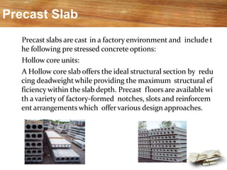
- 6. Precast Slab Precast slabs are cast in a factory environment and include t he following pre stressed concrete options: Hollow core units: A Hollow core slab offers the ideal structural section by redu cing deadweightwhile providing the maximum structural ef ficiency within the slab depth. Precast floors are available wi th a variety of factory-formed notches, slots and reinforcem ent arrangements which offervarious design approaches.
- 7. Precast Slab Double-tee units: Double Tee (TT) slabs are two symmetrically placed beams interacting w ith a slab forming in one section with a “double tee” shape made in preca st, pre stressed concrete. Resistant to moistureand corrosion. Parking garages, office buildings, co mmercial buildings, factories, industrial buildings, etc., are all ideal appli cations. Made with G50 concrete and ½” strands ASTM A416 as standard, each d ouble Tee slab is normally 2400mm wide.
- 8. BEARING SUPPORTS FOR DOUBLE TEE SLABS Double tee slabs can be supported on many types of suppo rts designed to carry the required dead and live loads. Preca st beams, precast walls, poured concrete beams and walls, m asonry walls, insulated concrete forming system walls and st ructural steel beams are all suitable for use with double tee s labs as load bearingsystems.
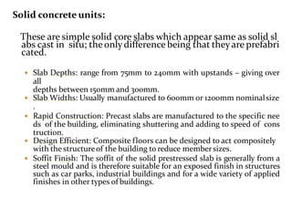
- 9. Solid concrete units: These are simple solid core slabs which appear same as solid sl abs cast in situ; theonlydifference being that theyare prefabri cated. Slab Depths: range from 75mm to 240mm with upstands – giving over all depths between 150mm and 300mm. Slab Widths: Usually manufactured to 600mm or 1200mm nominalsize . Rapid Construction: Precast slabs are manufactured to the specific nee ds of the building, eliminating shuttering and adding to speed of cons truction. Design Efficient: Composite floors can be designed to act compositely with the structureof the building to reduce membersizes. Soffit Finish: The soffit of the solid prestressed slab is generally from a steel mould and is therefore suitable for an exposed finish in structures such as car parks, industrial buildings and for a wide variety of applied finishes in other types of buildings.
- 10. Biaxial voided slabs : A relatively new technology developed in Europe has taken the efficienc y of cast-in-place flatplate slabs to new heights. Floor spans up to 17 meters (~56 feet) and overall slab thicknesses up to 60 cm (~24 inches). These slabs are more efficient than traditional structural floor systems commonly used in the construction of office buildings. The main effect of the voided slab system is to decrease the overall weight by as much as 35% when compared to a solid slab of the same capacity, while still offer ing otheradvantages. The voided slab system has the same bearing capacity as conventional c oncrete solid slabs, and standard design and detailing techniques can b e directlyapplied.
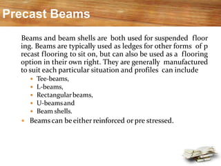
- 11. Precast Beams Beams and beam shells are both used for suspended floor ing. Beams are typically used as ledges for other forms of p recast flooring to sit on, but can also be used as a flooring option in their own right. They are generally manufactured to suit each particular situation and profiles can include Tee-beams, L-beams, Rectangularbeams, U-beamsand Beam shells. Beamscan beeitherreinforced or pre stressed.
- 12. Tee-Beams : Tee-beams (either single or double) cover the span range beyond slab-type members such as hollowcoreplanks. Tee-beamsare averyefficient structural shape. The units are generally cast with straight strands or defle cted strands, depending on designconsiderations. The Tee-beams are the basis for the design of economic al, fire rated structures where construction time, long s pans or heavy loadings are important cost influences.
- 13. Inverted Tee-Beams (Ledger) : Inverted Tee-beams are generally used for flooring syste ms like beam and infill where they provide a ledger for p recast floor units to sit on. Inverted Tee-beams are struct urallysimilar toa standard single Tee-beam.
- 14. L-Beam (Spandrel): L-beams havean 'L' shape profile which providesa ledge fora precast flooring system to sit on. These beamsare generally used tospan clearsections and are reinforced and/orprestressed.
- 15. Rectangular Beams: Rectangular beams get their name from the end profile. These beams are generally used to span clear sections an d are reinforced and/or prestressed. U-Beams: U-beams as the name suggests have a 'U' shaped profile. These beams are generally used to span clear sections an d are reinforced and/orpretensioned. used for single-unitmore commonly bridges than with composite f looring They are pedestrian systems.
- 16. Beam Shells: This is a complimentary composite system of precast elemnts that contain all the positive main beam reinforcement and m ost/all of the stirrups in a minimum volume of concrete for ec onomy and ease ofhandling. They are generally ‘U’ shaped and mostly used in conjunction with precast flooring such as hollowcore or permanent formw ork panels to eliminate on site forming.
- 17. Precast Columns Precast concrete columns are modular in design in o rder to be made intodifferent heights. Widths are 12", 18" and24". Columns are not structural, but can be used as such only after a structural engineer has adapted them to a building. Precast column can be produced as either single st orey corbel columnor multi storey corbel column.
- 18. Columns can either be rectangular or circular in sectio n. Projecting rebar can be provided for tying in to in-situ f loors. Options for foundation connections include cast i n base plates, dowel tubes or projections. Beam support is achieved by either flared heads, corbel s or bolt-onbrackets.
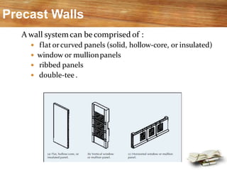
- 19. Precast Walls A wall systemcan be comprised of : flat orcurved panels (solid, hollow-core, or insulated) window or mullionpanels ribbed panels double-tee .
- 21. Precast Footings Precast footings are a recentinnovation. No holes need to be dug for footings, as the precast blocks are set on grade, and the posts, columns or b eams fit in pocketscast in the concrete block. Precast concrete foundations are pre-engineered sy stems manufactured in a controlledenvironment.
- 22. Precast footings Cast in situ footings •Built off site •Formed and cast on site •Lowest site impact (0.5-1.0 days) •High site impact (5-8 days) •Negligible impact by weather •Construction impacted by weather •Panelized = joints for expansion and Contraction •Monolithically cast = cracks
- 23. Type of Precast Systems The type of structural system in mind: The purpose of building, The efficiency of thesystem, The locationand The client’s need. Depending on the load-bearing structure, precast system s can be divided into the followcategories: Large-panel systems Framesystems Slab-column systems withwalls Mixed systems
- 24. Large panel system “Large-panel system” refers to multistory structures composed of large wall and floor concretepanels connected in thevertical and horizontal directions so that the wall panels enclose appropriate spaces for the ro oms within abuilding. These panels form a box-likestructure. Both vertical and horizontal panels resistgravity load. Wall panels are usually one storey high. Horizontal floor and roof panels span eitheras one-wayor two-w ay slabs. When properly joined together, these horizontal elements act as diaphragms that transfer the lateral loads to the walls.
- 25. Depending on wall layout, thereare three basic configurations of large- panel buildings: Cross-wall system : The main walls th at resist gravity and lateral loads are pla ced in the short direction of the buildin g. Longitudinal-wall system: The walls resisting gravity and lateral loads are pl aced in the longitudinaldirection. Two-way system. The walls are placed i n bothdirections.
- 26. Frame Systems Precast frames can be constructed using either linear elements orspatial beam column sub-assemblages. The use of linear elements generally means placing t he connecting faces at the beam-column junctions. The beams can be seated on corbels at the columns, for ease of construction and to aid the shear transfer from the beam to thecolumn. The beam-column joints accomplished in this way ar e hinged. However, rigid beam-column connections are used in some cases, when the continuity of longitudinal rei nforcement through the beam-column joint needs to be ensured.
- 27. The componentsof a precast reinforced concrete frame are shown inFigure:
- 28. Slab Column Systems These systems rely on shear walls to sustain lateral l oad effects, whereas the slab-column structure resist s mainly gravity loads. There are two main systems in this category: Lift-slab system withwalls Prestressed slab-columnsystem
- 29. Lift –slabsystem: The load-bearing structure consists of precast reinforced concrete columns andslabs. Precastcolumns areusually two stories high. All precast structural elements are assembled by means of special joints. Precast concrete floor slabs are lifted from the ground up to th e final height by liftingcranes. The slab panels are lifted to the top of the column and then moved downwards to the finalposition. Temporarysupports are used to keep the slabs in the position until theconnectionwith thecolumns has beenachieved.
- 30. The prestressed slab-columnsystem: Horizontal prestressing in two orthogonal directions to achi evecontinuity. The precastconcretecolumn elementsare 1 to 3 stories high. After erecting the slabs and columns of a storey, the columns a nd floor slabs are prestressed by means of prestressing tendon s that pass through ducts in the columns at the floor level and along the gaps left betweenadjacentslabs. After prestressing, the gaps between the slabs are filled with i n situ concrete and the tendons then become bonded with th e spans. post-tensioned slab columnconnection
- 31. References 1) “Building Construction” authored by S.C. Rangwala, Charotar publishing house Pvt. L td. 2) “Building Construction” authored by Bindra and Arora, Dhanpat Rai Publication. 3) “Building Construction” authored by M.L. Gambhir, Tata Meghraw Hills publication.