Shaft & keys (machine design & industrial drafting )
Download as PPTX, PDF10 likes3,687 views
This document discusses different types of shafts, keys, and their design considerations. It contains the following key points: 1. Shafts can be classified based on their shape (solid or hollow), application (transmitting, machine, spindle), and construction (rigid or flexible). 2. Keys are used to connect rotating machine elements to shafts and prevent relative motion. Common types include rectangular, square, parallel, gib-head, feather, and woodruff keys. 3. Shaft design considers factors like bending moment, shear stress, and material properties. Hollow shafts have higher strength-to-weight ratio than solid shafts of the same size.
1 of 34
Downloaded 83 times



Recommended
Design of bearing


Design of bearinggosavianiruddha Explains type and design procedure for bearings. Includes Numericals and questions based on bearings.
Design of Springs


Design of SpringsSurajKumarChand1 - The document discusses different types of springs including helical compression springs, helical extension springs, helical torsion springs, and multileaf springs.
- It describes the functions and applications of springs which include absorbing shocks and vibrations, storing energy, and measuring forces.
- Key terms related to helical spring design are defined such as wire diameter, mean coil diameter, spring index, solid length, compressed length, free length, and pitch. Stress and deflection equations for helical spring design are also presented.
Bearing 


Bearing Thriveni Earthmovers Pvt Lmt Bearings are used in machines to allow rotating parts to move freely while supporting loads. There are two main types of bearings: sliding contact/frictional bearings which operate on sliding friction; and rolling contact/anti-frictional bearings which have rolling elements like balls or rollers to reduce friction. Rolling contact bearings can carry heavier loads than sliding contact bearings and have lower friction, but are more complex and expensive to manufacture. Bearings are classified based on the type of load they support, such as radial loads, axial/thrust loads, or combined loads. Common bearing types include ball bearings, roller bearings, tapered roller bearings, and needle roller bearings.
Unit 3 design against fluctuation load


Unit 3 design against fluctuation loadSomnath Kolgiri The document discusses stress concentration and fatigue failure in machine elements. It defines stress concentration as the localization of high stresses due to irregularities or abrupt changes in cross-section. Stress concentration can be reduced by avoiding sharp changes in cross-section and providing fillets and chamfers. Fatigue failure occurs when fluctuating stresses cause cracks over numerous load cycles. The endurance limit is the maximum stress amplitude that causes failure after an infinite number of cycles. Factors like stress concentration, surface finish, size, and mean stress affect the endurance limit. Designs should minimize stress raisers and protect against corrosion to prevent fatigue failures.
Spur gears


Spur gearsHareesha N Gowda, Dayananda Sagar College of Engg, Bangalore Unit 6- spur gears, Kinematics of machines of VTU Syllabus prepared by Hareesha N Gowda, Asst. Prof, Dayananda Sagar College of Engg, Blore. Please write to hareeshang@gmail.com for suggestions and criticisms.
Screw Jack Design


Screw Jack DesignKunind Sharma The document describes the design of a screw jack that can lift up to 3 tons. It identifies the need, outlines the research conducted, and describes the components designed. The team designed a screw, nut, handle, frame, and cup. Design calculations were performed to determine specifications. Materials were selected based on withstanding torsional, bending and axial loads. The conclusion discusses using a 5/8" acme power screw and improving the design with a two start thread and longer handle to reduce required force.
Design of shafts couplings ppt


Design of shafts couplings pptnsvnhanu 1. Shaft couplings are used to connect shafts that are manufactured separately or to introduce flexibility between shafts. The main types are rigid and flexible couplings.
2. Rigid couplings transmit torque without losses but require perfectly aligned shafts. Flexible couplings allow for misalignment. Common rigid couplings are sleeve, clamp, and flange couplings.
3. Flange couplings use separate cast iron flanges keyed to each shaft end and bolted together. The flanges and bolts are designed to transmit the torque between the shafts. Flexible couplings like bush pin couplings introduce mechanical flexibility.
Bearing


BearingRuchika Panchal The document is a presentation on bearings created by Akash Panchal. It discusses the definition of a bearing, provides a brief history, and examines various types of bearings like ball bearings, roller bearings, plain bearings, and their functions. It also looks at bearing selection, arrangement, lubrication, and life calculation. The presentation contains several diagrams and is intended to provide an overview of bearings.
Bearing and Sliding contact bearings


Bearing and Sliding contact bearingsdodi mulya This document provides information on bearings, including their history, classification, materials used, lubrication types, and design procedures. It discusses how bearings are designed to reduce friction, carry loads, and guide moving parts. The key types are described as radial or thrust bearings, and sliding or rolling contact bearings. Common materials include babbitt metals, bronzes, cast iron, silver, and non-metallic options. Design of journal bearings involves calculating parameters like load capacity, pressure, clearance, heat generation and dissipation. An example at the end illustrates the full design process.
Design of helical spring


Design of helical springKunj Thummar This is a power point presentation on the design of Helical springs subjected to Static and Fluctuating load. It is part of Design of Machine elements subject.
Unit1 designof levers


Unit1 designof leversSomnath Kolgiri This document discusses the design of various types of levers, including hand levers, foot levers, and bell crank levers. It begins with an introduction to levers and their uses. The main types of levers are then described: one arm lever, two arm lever, and angular/bell crank lever. Design considerations for hand levers and foot levers are provided, including calculating the diameter of the shaft, dimensions of keys and bosses, and cross-sectional dimensions of the lever arm. Design of bell crank levers is also covered. Examples and problems for calculating lever dimensions are given. The document concludes with a brief mention of designing C-clamps and offset links.
Rolling contact bearings


Rolling contact bearingsdodi mulya Rolling Contact Bearing, Selection of Rolling Contact Bearings, Machine Element Design, Bantalan Gelinding, Pemilihan Bantalan Gelinding, Perancangan Elemen Mesin
1.4 law of gearing


1.4 law of gearingKiran Wakchaure This document discusses the law of gearing in three main points:
1) The common normal at the point of contact between gear teeth must always pass through the pitch point. This is the fundamental condition for designing gear teeth profiles.
2) The angular velocity ratio between two gears must remain constant throughout meshing.
3) The angular velocity ratio is inversely proportional to the ratio of the distances of the pitch point P from the gear centers O1 and O2. The common normal intersecting the line of centers at P divides the center distance inversely proportional to the angular velocity ratio.
Introduction & Design of Bevel Gears


Introduction & Design of Bevel GearsDhrumit Patel Bevel gears are used to transmit motion between two intersecting shafts at any angle. The design procedure involves selecting materials, tooth profiles, and module based on requirements and strength calculations. Bevel gears are then designed with the proper diameters, cone distance, and face width. Design is checked for surface and bending stresses. Bevel gears are commonly used in differentials and hand drills to change the direction of rotation. They allow transmission of power between non-parallel shafts but require precise mounting and bearings.
Unit 2 design of shaft


Unit 2 design of shaftSomnath Kolgiri 1. A shaft transmits power and rotational motion and has machine elements like gears and pulleys mounted on it.
2. Press fits, keys, dowel pins, and splines are used to attach machine elements to the shaft.
3. The shaft rotates on rolling contact or bush bearings and uses features like retaining rings to take up axial loads.
4. Couplings are used to transmit power between drive and driven shafts like between a motor and gearbox.
Whirling of shaft


Whirling of shaftPrem Kumar Soni Whirling of shafts occurs due to rotational imbalance of a shaft, even in the absence of external loads, which causes resonance to occur at certain speeds, known as critical speeds.
Uint 1 locating and clamping devices


Uint 1 locating and clamping devicesS.DHARANI KUMAR This document provides definitions and principles related to locating and clamping in jigs and fixtures design. It defines a jig as a device that holds work and locates the tool path, and a fixture as a device that locates work on a machine table. It discusses locating principles like six point location and 3-2-1 principle. It also covers various locating and clamping devices like pins, buttons, V-locators, and different types of clamps. The document aims to provide fundamental guidelines for effective design of jigs and fixtures.
Milling Fixture


Milling FixtureAmruta Rane The document discusses milling fixtures and their components. Milling fixtures securely hold workpieces for milling operations. They have locating elements to precisely position workpieces and clamping elements to securely hold them against cutting forces. Key components of milling fixtures include a base, tenons to locate the fixture on the machine table, setting blocks to position cutters, and clamps or vices to hold workpieces in place. Different types of milling fixtures are used for operations like face milling or gang milling and can have mechanical, hydraulic or pneumatic clamping systems.
Types of fits


Types of fitsSinokia Lee The document describes different types of fits between mating parts in an assembly: clearance fit, transition fit, and interference fit. Clearance fit has a gap between parts, transition fit is neither loose nor tight, and interference fit has no gap and requires parts to be forced together. Each fit type is further broken down, defining features and common examples.
Turning fixtures


Turning fixturesGuhan M The document discusses different types of turning fixtures and mandrels used to securely hold workpieces for machining operations on lathes. Turning fixtures are cheaper than milling and allow for asymmetric jobs to be machined. Fixtures must be carefully designed for operator safety, accuracy, and proper clamping to the faceplate. Mandrels are used internally to locate cylindrical workpieces and come in tapered, clamping, expanding, and threaded varieties to suit a range of bore sizes and provide accurate concentricity.
Unit 2 Design Of Shafts Keys and Couplings


Unit 2 Design Of Shafts Keys and CouplingsMahesh Shinde This document provides information about the design of shafts, keys, and couplings. It discusses transmission shafts, stresses induced in shafts, and shaft design based on strength and rigidity. It presents formulas for shaft design using maximum shear stress theory, distortion energy theory, and the ASME code. Several examples are provided to demonstrate how to calculate the diameter of a shaft given the power transmitted, loads on the shaft, material properties, and other parameters using these theories and codes. Assignments involving similar calculations of shaft diameters are presented.
12 Speed Gear Box Theory Notes by Prof. Sagar Dhotare


12 Speed Gear Box Theory Notes by Prof. Sagar DhotareSagar Dhotare It contains the following points:-
Requirements of speed gearboxes
Methods for changing speed in gearboxes
Preferred Numbers
Step ratio (or series ratio or progression ratio) (∅)
RAY DIAGRAM (OR SPEED DIAGRAM)
KINEMATIC LAYOUT (OR KINEMATIC ARRANGEMENT)
BASIC RULES FOR OPTIMUM GEARBOX DESIGN
DESIGN OF SOLID TRANSMISSION SHAFT


DESIGN OF SOLID TRANSMISSION SHAFTAnimesh Bhattacharya The document discusses transmission shafts and their design. It defines a transmission shaft as a rotating element that supports transmission elements like gears and transmits power. Stepped shafts are commonly used, with maximum diameter in the middle and minimum at the ends. Shaft material is typically carbon steel. Design considers strength based on stresses from loads, torsional rigidity based on permissible twist, and ASME code factors for shock/fatigue. Equivalent moment concepts are introduced for combined loading conditions.
Design of couplings


Design of couplingsM.D.Raj Kamal The document discusses the design of various types of rigid and flexible couplings. It provides steps to design a flange coupling connecting two shafts transmitting 37.5 kW power at 180 rpm. Key details include calculating torque from power, selecting shaft diameter, coupling dimensions based on standards, and checking design of key and bolts for shearing and crushing. The document also provides problems and solutions for designing flange, muff, and clamp couplings for given power and speed conditions.
Unit 2.3 Design of Coupling


Unit 2.3 Design of CouplingYugal Kishor Sahu A coupling is a mechanical device that rigidly joins two rotating shafts together. There are three main types of couplings: rigid couplings for perfectly aligned shafts, flexible couplings for shafts with misalignment, and flange couplings which can transmit high torque capacities but do not tolerate misalignment or shocks/vibrations. Design of couplings involves calculating shaft diameters, sleeve/flange dimensions, key dimensions, and bolt diameters based on the transmitted power, material properties, and safety factors. Dimensional relationships and equations are used to check stresses in the various coupling components.
Spur gear and design of spur gear


Spur gear and design of spur gearYash Shah This presentation contains basic idea regarding spur gear and provides the best equations for designing of spur gear. One can Easily understand all the parameters required to design a Spur Gear
Manual part programming


Manual part programmingjntuhcej difference of NC and CNC ,Part programming,Methods of manual part programming,Basic CNC input data,Preparatory Functions ,Miscellaneous Functions,Interpolation:Canned cycles:part programming on component,Tool length compensation,Cutter Radius,Task compensation:Types of media of NC
ME6503 - DESIGN OF MACHINE ELEMENTS UNIT - V NOTES


ME6503 - DESIGN OF MACHINE ELEMENTS UNIT - V NOTESASHOK KUMAR RAJENDRAN ME6503 - DESIGN OF MACHINE ELEMENTS UNIT - V NOTES
THE QUESTION NUMBER WILL MATCH TO THE QUESTION BANK ATTACHED AT THE END
Unit1 161021055929


Unit1 161021055929shushay hailu This document provides an introduction to machine elements and power transmission devices taught in the second semester of a mechanical engineering course. It discusses various machine elements like shafts, keys, couplings, bearings, clutches, and brakes. For power transmission devices, it covers belts, chains, and gear drives. The introduction describes machine elements as components that perform specific functions like holding parts together, transmitting power, or providing support. It then categorizes common elements and provides examples.
BASIC MECHANICAL ENGINEERING


BASIC MECHANICAL ENGINEERINGNAGorao SURNER This document provides an introduction to machine elements and power transmission devices taught in the second semester of a mechanical engineering course. It discusses various machine elements like shafts, keys, couplings, bearings, clutches, and brakes. It also covers power transmission devices such as belt drives, chain drives, and gear drives. The document describes the function, types, materials, and design of these common mechanical components.
More Related Content
What's hot (20)
Bearing and Sliding contact bearings


Bearing and Sliding contact bearingsdodi mulya This document provides information on bearings, including their history, classification, materials used, lubrication types, and design procedures. It discusses how bearings are designed to reduce friction, carry loads, and guide moving parts. The key types are described as radial or thrust bearings, and sliding or rolling contact bearings. Common materials include babbitt metals, bronzes, cast iron, silver, and non-metallic options. Design of journal bearings involves calculating parameters like load capacity, pressure, clearance, heat generation and dissipation. An example at the end illustrates the full design process.
Design of helical spring


Design of helical springKunj Thummar This is a power point presentation on the design of Helical springs subjected to Static and Fluctuating load. It is part of Design of Machine elements subject.
Unit1 designof levers


Unit1 designof leversSomnath Kolgiri This document discusses the design of various types of levers, including hand levers, foot levers, and bell crank levers. It begins with an introduction to levers and their uses. The main types of levers are then described: one arm lever, two arm lever, and angular/bell crank lever. Design considerations for hand levers and foot levers are provided, including calculating the diameter of the shaft, dimensions of keys and bosses, and cross-sectional dimensions of the lever arm. Design of bell crank levers is also covered. Examples and problems for calculating lever dimensions are given. The document concludes with a brief mention of designing C-clamps and offset links.
Rolling contact bearings


Rolling contact bearingsdodi mulya Rolling Contact Bearing, Selection of Rolling Contact Bearings, Machine Element Design, Bantalan Gelinding, Pemilihan Bantalan Gelinding, Perancangan Elemen Mesin
1.4 law of gearing


1.4 law of gearingKiran Wakchaure This document discusses the law of gearing in three main points:
1) The common normal at the point of contact between gear teeth must always pass through the pitch point. This is the fundamental condition for designing gear teeth profiles.
2) The angular velocity ratio between two gears must remain constant throughout meshing.
3) The angular velocity ratio is inversely proportional to the ratio of the distances of the pitch point P from the gear centers O1 and O2. The common normal intersecting the line of centers at P divides the center distance inversely proportional to the angular velocity ratio.
Introduction & Design of Bevel Gears


Introduction & Design of Bevel GearsDhrumit Patel Bevel gears are used to transmit motion between two intersecting shafts at any angle. The design procedure involves selecting materials, tooth profiles, and module based on requirements and strength calculations. Bevel gears are then designed with the proper diameters, cone distance, and face width. Design is checked for surface and bending stresses. Bevel gears are commonly used in differentials and hand drills to change the direction of rotation. They allow transmission of power between non-parallel shafts but require precise mounting and bearings.
Unit 2 design of shaft


Unit 2 design of shaftSomnath Kolgiri 1. A shaft transmits power and rotational motion and has machine elements like gears and pulleys mounted on it.
2. Press fits, keys, dowel pins, and splines are used to attach machine elements to the shaft.
3. The shaft rotates on rolling contact or bush bearings and uses features like retaining rings to take up axial loads.
4. Couplings are used to transmit power between drive and driven shafts like between a motor and gearbox.
Whirling of shaft


Whirling of shaftPrem Kumar Soni Whirling of shafts occurs due to rotational imbalance of a shaft, even in the absence of external loads, which causes resonance to occur at certain speeds, known as critical speeds.
Uint 1 locating and clamping devices


Uint 1 locating and clamping devicesS.DHARANI KUMAR This document provides definitions and principles related to locating and clamping in jigs and fixtures design. It defines a jig as a device that holds work and locates the tool path, and a fixture as a device that locates work on a machine table. It discusses locating principles like six point location and 3-2-1 principle. It also covers various locating and clamping devices like pins, buttons, V-locators, and different types of clamps. The document aims to provide fundamental guidelines for effective design of jigs and fixtures.
Milling Fixture


Milling FixtureAmruta Rane The document discusses milling fixtures and their components. Milling fixtures securely hold workpieces for milling operations. They have locating elements to precisely position workpieces and clamping elements to securely hold them against cutting forces. Key components of milling fixtures include a base, tenons to locate the fixture on the machine table, setting blocks to position cutters, and clamps or vices to hold workpieces in place. Different types of milling fixtures are used for operations like face milling or gang milling and can have mechanical, hydraulic or pneumatic clamping systems.
Types of fits


Types of fitsSinokia Lee The document describes different types of fits between mating parts in an assembly: clearance fit, transition fit, and interference fit. Clearance fit has a gap between parts, transition fit is neither loose nor tight, and interference fit has no gap and requires parts to be forced together. Each fit type is further broken down, defining features and common examples.
Turning fixtures


Turning fixturesGuhan M The document discusses different types of turning fixtures and mandrels used to securely hold workpieces for machining operations on lathes. Turning fixtures are cheaper than milling and allow for asymmetric jobs to be machined. Fixtures must be carefully designed for operator safety, accuracy, and proper clamping to the faceplate. Mandrels are used internally to locate cylindrical workpieces and come in tapered, clamping, expanding, and threaded varieties to suit a range of bore sizes and provide accurate concentricity.
Unit 2 Design Of Shafts Keys and Couplings


Unit 2 Design Of Shafts Keys and CouplingsMahesh Shinde This document provides information about the design of shafts, keys, and couplings. It discusses transmission shafts, stresses induced in shafts, and shaft design based on strength and rigidity. It presents formulas for shaft design using maximum shear stress theory, distortion energy theory, and the ASME code. Several examples are provided to demonstrate how to calculate the diameter of a shaft given the power transmitted, loads on the shaft, material properties, and other parameters using these theories and codes. Assignments involving similar calculations of shaft diameters are presented.
12 Speed Gear Box Theory Notes by Prof. Sagar Dhotare


12 Speed Gear Box Theory Notes by Prof. Sagar DhotareSagar Dhotare It contains the following points:-
Requirements of speed gearboxes
Methods for changing speed in gearboxes
Preferred Numbers
Step ratio (or series ratio or progression ratio) (∅)
RAY DIAGRAM (OR SPEED DIAGRAM)
KINEMATIC LAYOUT (OR KINEMATIC ARRANGEMENT)
BASIC RULES FOR OPTIMUM GEARBOX DESIGN
DESIGN OF SOLID TRANSMISSION SHAFT


DESIGN OF SOLID TRANSMISSION SHAFTAnimesh Bhattacharya The document discusses transmission shafts and their design. It defines a transmission shaft as a rotating element that supports transmission elements like gears and transmits power. Stepped shafts are commonly used, with maximum diameter in the middle and minimum at the ends. Shaft material is typically carbon steel. Design considers strength based on stresses from loads, torsional rigidity based on permissible twist, and ASME code factors for shock/fatigue. Equivalent moment concepts are introduced for combined loading conditions.
Design of couplings


Design of couplingsM.D.Raj Kamal The document discusses the design of various types of rigid and flexible couplings. It provides steps to design a flange coupling connecting two shafts transmitting 37.5 kW power at 180 rpm. Key details include calculating torque from power, selecting shaft diameter, coupling dimensions based on standards, and checking design of key and bolts for shearing and crushing. The document also provides problems and solutions for designing flange, muff, and clamp couplings for given power and speed conditions.
Unit 2.3 Design of Coupling


Unit 2.3 Design of CouplingYugal Kishor Sahu A coupling is a mechanical device that rigidly joins two rotating shafts together. There are three main types of couplings: rigid couplings for perfectly aligned shafts, flexible couplings for shafts with misalignment, and flange couplings which can transmit high torque capacities but do not tolerate misalignment or shocks/vibrations. Design of couplings involves calculating shaft diameters, sleeve/flange dimensions, key dimensions, and bolt diameters based on the transmitted power, material properties, and safety factors. Dimensional relationships and equations are used to check stresses in the various coupling components.
Spur gear and design of spur gear


Spur gear and design of spur gearYash Shah This presentation contains basic idea regarding spur gear and provides the best equations for designing of spur gear. One can Easily understand all the parameters required to design a Spur Gear
Manual part programming


Manual part programmingjntuhcej difference of NC and CNC ,Part programming,Methods of manual part programming,Basic CNC input data,Preparatory Functions ,Miscellaneous Functions,Interpolation:Canned cycles:part programming on component,Tool length compensation,Cutter Radius,Task compensation:Types of media of NC
ME6503 - DESIGN OF MACHINE ELEMENTS UNIT - V NOTES


ME6503 - DESIGN OF MACHINE ELEMENTS UNIT - V NOTESASHOK KUMAR RAJENDRAN ME6503 - DESIGN OF MACHINE ELEMENTS UNIT - V NOTES
THE QUESTION NUMBER WILL MATCH TO THE QUESTION BANK ATTACHED AT THE END
Similar to Shaft & keys (machine design & industrial drafting ) (20)
Unit1 161021055929


Unit1 161021055929shushay hailu This document provides an introduction to machine elements and power transmission devices taught in the second semester of a mechanical engineering course. It discusses various machine elements like shafts, keys, couplings, bearings, clutches, and brakes. For power transmission devices, it covers belts, chains, and gear drives. The introduction describes machine elements as components that perform specific functions like holding parts together, transmitting power, or providing support. It then categorizes common elements and provides examples.
BASIC MECHANICAL ENGINEERING


BASIC MECHANICAL ENGINEERINGNAGorao SURNER This document provides an introduction to machine elements and power transmission devices taught in the second semester of a mechanical engineering course. It discusses various machine elements like shafts, keys, couplings, bearings, clutches, and brakes. It also covers power transmission devices such as belt drives, chain drives, and gear drives. The document describes the function, types, materials, and design of these common mechanical components.
Keys


Keysabdul ahad noohani Keys are used to connect two coaxial shafts to transmit power. There are several types of keys including sunk keys, saddle keys, tangent keys, and round keys. Sunk keys like rectangular, square, parallel, gib-head, and feather keys are common. Woodruff keys allow for easy adjustment. The key length must be sufficient to transmit the full torque of the shaft based on shear strength calculations. A keyway weakens the shaft so its dimensions are important. Splined shafts can transmit more power than a single keyed shaft.
Machine elements, Power Transmission Devices.pdf


Machine elements, Power Transmission Devices.pdfSitiasma24 The document provides an introduction to mechanical engineering concepts including machine elements and power transmission devices. It describes functions, sketches and uses of common machine elements like shafts, axles, keys, couplings, bearings, clutches and brakes. It also discusses construction, working and applications of power transmission devices including belt drives, chain drives and gear drives. The document contains detailed information on various types of each machine element and power transmission device.
Design of keys


Design of keysSaravanakumar Sengottaiyan This document discusses different types of keys used to connect a shaft to a pulley or gear. It describes sunk keys like rectangular, square, parallel, gib-head, feather, and woodruff keys. It also covers saddle keys, tangent keys, round keys, and splined shafts. The key transmits torque from the shaft and can fail due to shearing or crushing stresses. For a key to be equally strong against both types of stresses, it should have a square cross-section where the width and thickness are equal.
Types of key


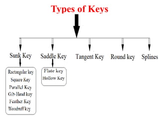
Types of keyPREM BAGADE Sunk keys
a) Rectangular sunk key
b) Square sunk key
c) Parallel sunk key
d) Gib-head key
e) Feather key
f) Woodruff key
2)Saddle keys
a)Flat saddle key
b) Hollow saddle key
3) Tangent keys
4) Round keys
5) Splines
Design of Keys.ppt


Design of Keys.pptRamaSamy Veeramalai Keys are used to connect a shaft to a pulley or gear. There are different types of keys including sunk keys, saddle keys, tangent keys, round keys, and splines. Sunk keys can be rectangular, square, parallel, or have a gib head. Woodruff keys are tapered and accommodate misalignment. Splined shafts have integral keys and allow for axial movement. Crankshafts convert reciprocating to rotary motion and can have single or multiple throws. Forces induce bending and shear stresses that must be within allowable limits during design. Materials like carbon and alloy steels are used for crankshafts.
1588433152-lecture-2.pptx


1588433152-lecture-2.pptxKhalil Alhatab Keys are used to connect a shaft to a pulley or hub to prevent relative motion. There are different types of keys including sunk keys, saddle keys, tangent keys, round keys, and splines. Sunk keys are the most common and include rectangular, square, parallel, gib-head, and feather keys. Keys transmit torque through both shearing and crushing stresses. The maximum torque a shaft can withstand depends on the shear stress limit and its polar moment of inertia.
Unit i Intro To mechanical Engineering


Unit i Intro To mechanical EngineeringAISSMS IOIT,PUNE This document discusses machine elements and power transmission devices used in mechanical engineering. It describes common machine elements like shafts, axles, keys, couplings, bearings, clutches, and brakes. It provides details on their functions, types, materials, and uses. Power transmission devices covered include belt drives, chain drives, and gear drives. Shafts are classified as machine shafts and transmission shafts. Different types of shafts and keys are defined along with their applications in power transmission.
Lathe parts


Lathe partskempaRaju5 The document provides information about lathes. It begins with an introduction that describes how a lathe works by rotating a workpiece against a stationary cutting tool. It then discusses the history of lathes, including their use in France in 1569 and adaptation for metal cutting during the Industrial Revolution in England. The document also covers the inventor of the center lathe, Henry Maudsley, and includes diagrams of different lathe parts and types.
Keys


KeysAbdul Rauf Noohani The document discusses different types of keys used to connect rotating shafts, including:
- Sunk keys like rectangular, square, parallel, gib-head, feather, and woodruff keys
- Saddle keys that are flat or hollow for lighter loads
- Tangent keys fitted in pairs at right angles to withstand torque
- Round keys that fit into drilled holes for low power drives
It also covers splined shafts that have multiple integral keys for transmitting larger forces compared to a single keyed shaft. The keys are designed based on withstanding shear and crushing stresses from the transmitted torque.
Machine design


Machine designArunendra Nath Chaubey This document provides an overview of machine design topics including joints, fasteners, springs, and bearings. It discusses common joint types like knuckle and cotter joints. For springs, it covers material selection criteria and types like helical and leaf springs. Bearing types include ball, roller, hydrodynamic, and hydrostatic with descriptions of functions and examples. The document also examines design of keys including sunk, saddle, tangent, round, and splined varieties.
machine design lecture topic 2.0-Keys.pdf


machine design lecture topic 2.0-Keys.pdfCrisIvhanBermas Keys are used to prevent relative rotation between circular shafts and mating parts. Common types include square, feather, woodruff, and gib head keys. Key design considers the shear and compressive stresses on the key and mating parts. The key length is calculated based on the torque transmitted, shaft diameter, key dimensions, and allowable stresses of the materials. Safety factors of 1.5-4.5 are used depending on the load conditions. Examples show calculating key dimensions, transmitted torque, and horsepower based on given shaft properties and design stresses.
Shaft


ShaftBrajesh Kashyap The document discusses various types of shafts and shaft couplings. It provides information on shaft materials, sizing, layout and design considerations. Regarding couplings, it describes rigid couplings like sleeve, flange and marine couplings. It also discusses flexible bush pin couplings. Key points covered include shaft material selection, stress analysis for sizing, deflection requirements, coupling design for strength, rigidity and alignment between connected shafts. Common shaft and coupling types, their designs and applications are explained.
Keys


KeysMRNOOBLite This document provides information about the Machine Design-I course including the instructor's details, textbook and reference books, sessional marks distribution, and a note about important topics for exams. It then discusses the topic of shafts, keys, and couplings. Different types of keys like sunk, saddle, and spline keys are described along with their dimensions. The forces acting on sunk keys and formulas for calculating torque transmitted by solid and hollow shafts are provided. Finally, various types of rigid and flexible couplings are defined including sleeve, clamp, flange, bushed pin, universal and Oldham couplings.
Unit 4 Design of Power Screw and Screw Jack


Unit 4 Design of Power Screw and Screw JackMahesh Shinde The document discusses power screws, including their terminology, types of threads, torque analysis, and efficiency. It defines key terms like nominal diameter, pitch, lead, and lead angle. It describes common types of threads like square, ACME, and buttress threads. It discusses torque required to raise and lower loads, including expressions for self-locking and overhauling screws. The document also covers screw efficiency and collar friction torque, providing expressions to calculate overall efficiency. An example calculation is given to find maximum load lifted, efficiency, and overall efficiency of a screw jack.
Lathe machine 


Lathe machine DarshanKumar136 The document discusses various types of lathe machines and their components and operations. It begins with an introduction to lathes, describing them as important metalworking tools that rotate the workpiece while a cutting tool shapes it. It then explains different lathe types like engine lathes, speed lathes, and CNC lathes. The main lathe components discussed are the bed, headstock, tailstock, carriage, and lead screw. Common lathe operations like turning, threading, boring, drilling and tapering are also summarized.
Turning Machines


Turning Machineslaxtwinsme Henry Maudslay is considered the father of machine tool technology for his inventions around 1800, including a metal lathe that enabled mass production with interchangeable parts. A lathe is used to machine cylindrical workpieces and consists of main parts like the bed, headstock, tailstock, carriage, and tool post. Different lathe types include engine lathes, turret lathes, and automatic lathes. The document discusses lathe parts and mechanisms in detail.
2. lathe


2. latheProf.Mayur Modi METAL CUTTING, LATHE MACHINE,LATHE OPERATIONS, ALLIGNMENT TEST ON LATHE MACHINE, TYPES OF LATHE MACHINES
unit-iii-lathe.ppt


unit-iii-lathe.pptVishalini33 Mechanical engineering is an interdisciplinary field that requires diverse skills. Mechanical engineers play an important role on design teams and must understand forces across multiple engineering disciplines. Lathes and drilling machines are fundamental machine tools used for machining operations like cutting, shaping, and forming metals. A lathe consists of major components like the bed, headstock, tailstock, and carriage that work together to perform operations such as turning, facing, drilling, and threading.
More from Digvijaysinh Gohil (20)
Hydraulic cranes


Hydraulic cranesDigvijaysinh Gohil Hydraulic cranes use pressurized water to move a sliding ram connected to a movable pulley block, which controls the distance between the pulley blocks and lifts and lowers loads attached to a hoist cable. The crane consists of a vertical post with a jib and tie beams, guide pulleys, and a hydraulic jigger cylinder. Hydraulic cranes are widely used to lift heavy loads in shipping, warehouses, workshops, and other industrial applications.
Hydraulic braking systems


Hydraulic braking systemsDigvijaysinh Gohil This document discusses hydraulic braking systems. It explains that hydraulics uses pressurized fluids to transmit and increase force. Hydraulic braking systems use this principle to transmit pressure from the brake pedal through fluid to the calipers or wheel cylinders to create braking force. It describes different types of braking systems like drum, disc, and dual systems as well as components like the master cylinder, calipers, and proportioning valves which are used to balance braking force.
Human resources management


Human resources managementDigvijaysinh Gohil Tata Motors is a global automotive manufacturing company founded in 1868 and headquartered in Mumbai, India. It has over 600,000 employees operating in over 100 countries, generating $108.78 billion in annual revenue, with 68% from international markets. The company focuses on developing its large pool of technical and managerial talent through extensive training programs and career development schemes. Its human resources practices emphasize framing HR policies, identifying employee talents, improving productivity, and optimally utilizing human resources to achieve organizational objectives.
Traits of a good listner (Communication Skills)


Traits of a good listner (Communication Skills)Digvijaysinh Gohil To be a good listener, one must practice active listening skills like being non-evaluative, paraphrasing the speaker's message, reflecting implications and hidden feelings, inviting further contributions, and responding non-verbally. It is important to communicate that the speaker is being heard and understood without judging their ideas, attitudes, or values. Clarifying points by paraphrasing ensures accurate understanding, while reflecting on where the speaker's ideas are leading shows engagement and encourages expansion on their thoughts. Developing an attitude of tolerance, acceptance, and understanding takes effort but allows for effective communication.
Techniques of reading (Communication Skills)


Techniques of reading (Communication Skills)Digvijaysinh Gohil The document discusses six techniques of reading:
1. Skimming and scanning allow for reading large amounts of material quickly to find specific information or get a general idea.
2. Exploratory reading is used to gain a general understanding of main ideas and relate new information to what is already known.
3. Intensive and analytical/critical reading involve reading slowly and carefully to gain maximum understanding and evaluate or reflect on the content. Words per minute is lowest with these techniques.
Proxemics (2) (Communication Skills)


Proxemics (2) (Communication Skills)Digvijaysinh Gohil The document discusses the concept of proxemics, which is the study of how people use physical space in social interactions and communications. It notes that space is used to signal power, status, and relationships. It outlines Edward T. Hall's model of four distinct interpersonal distance zones - intimate, personal, social, and public - and discusses behavioral norms and communication styles appropriate for each zone.
Paralinguistic (Communication Skills)


Paralinguistic (Communication Skills)Digvijaysinh Gohil This document discusses three aspects of voice and speech: volume, pitch, and articulation. It notes that volume should be adjusted based on the size of the speaking area, with larger areas requiring higher volume. Pitch refers to the vibrations per second of the voice and impacts the conveyed emotions. Articulation means speaking distinctly and crisply producing each sound. The document advises developing clear articulation skills.
Paralinguistic (2) (Communication Skills)


Paralinguistic (2) (Communication Skills)Digvijaysinh Gohil Paralinguistic refers to non-verbal communication through voice. It includes characteristics like quality, volume, pace, pitch, and articulation of one's voice. Quality refers to the unique characteristics of an individual's voice, volume depends on whether the speaking environment is large or small, pace is ideally between 120-150 words per minute, pitch conveys emotions, and clear articulation helps the audience understand.
Paralinguistic (1) (Communication Skills)


Paralinguistic (1) (Communication Skills)Digvijaysinh Gohil This document discusses paralinguistic features of speech, which are non-verbal elements that contribute meaning. It describes qualities like voice, volume, rate, pitch, articulation, pronunciation, and pause. Specific qualities like voice quality, volume, pace/rate, pitch, articulation, pronunciation, and modulation are defined. Voice quality can distinguish individuals and be resonant, soft, thin, hoarse, or harsh. Volume should project but not always be loud. Pace/rate should vary between 120-150 words per minute. Pitch varies with intonation and emotion. Articulation and pronunciation impact credibility if words are slurred or mispronounced. Modulation prevents dullness through word and sentence stress. Pauses
Organizing a contents & preparing an outline


Organizing a contents & preparing an outlineDigvijaysinh Gohil This document provides guidance on organizing content and preparing an outline for a presentation. It recommends dividing a presentation into three parts: an introduction, main body, and conclusion. The introduction should include an opening statement to engage the audience, the purpose of the presentation, and an overview of what will be discussed. The main body can be organized chronologically, categorically, by causes and effects, or with a problem-solution structure depending on the topic. It should cover the key points in a logical sequence. The conclusion should review the main ideas and remind the audience of the purpose. It also provides steps for creating an outline, including determining the theme, gathering relevant information, identifying main points, organizing the material logically, and refining the
Organizing a contents & preparing an outline (2)


Organizing a contents & preparing an outline (2)Digvijaysinh Gohil This document provides guidance on organizing content and preparing an outline for a presentation. It recommends dividing a presentation into three parts: introduction, main body, and conclusions. The introduction should catch the audience's attention with an opening statement and state the purpose. The main body can be organized chronologically, categorically, with a cause-and-effect structure, or with a problem-solution approach. The conclusions should briefly review the main points and remind the audience of the purpose without adding new information. An outline should identify the main idea, gather relevant information, select the main points, organize the material logically, write an engaging introduction and conclusion, and be refined through practice.
Kinesics (Communication Skills)


Kinesics (Communication Skills)Digvijaysinh Gohil This document discusses various forms of nonverbal communication including kinesics, posture, gesture, eye contact, facial expression, and personal appearance. Kinesics refers to body movements and postures that convey meaning. Posture can indicate attention level and mirroring postures leads to positive perceptions. Gestures supplement verbal communication and emblems are culture-specific gestures. Eye contact norms differ across cultures. Facial expressions communicate emotions. Personal appearance such as clothing can influence judgments of a person.
Kinesics (3) (Communication Skills)


Kinesics (3) (Communication Skills)Digvijaysinh Gohil Kinesics is the study of non-verbal communication through body movement and physical gestures. Non-verbal communication conveys messages simultaneously with verbal communication during face-to-face interactions. It includes five parts: personal appearance, posture, gestures, facial expressions, and eye contact. Personal appearance, posture, and gestures can reveal personality and attitudes. Facial expressions and eye contact provide additional cues about emotions and truthfulness beyond what is said verbally.
Kinesics (2) (Communication Skills)


Kinesics (2) (Communication Skills)Digvijaysinh Gohil Kinesics refers to body language and non-verbal communication. It includes elements like personal appearance, posture, gestures, facial expressions, and eye contact. These all convey messages without words. For example, posture can indicate comfort, domination, or inferiority. Facial expressions like smiles or frowns also communicate feelings. Eye contact is a powerful form of non-verbal communication that can reveal attitudes and feelings. Kinesics plays an important role in presentations and interactions.
Introduction to communication (Communication Skills)


Introduction to communication (Communication Skills)Digvijaysinh Gohil This document discusses communication and is presented by Harsh Patel. It defines communication as the process of exchanging information, ideas, thoughts, feelings and emotions through speech, signals, writing or behavior. It outlines the process of communication and describes the main types of communication as verbal and nonverbal. Verbal communication is transmitted through words, either orally or in writing, while nonverbal communication involves wordless messages through gestures, body language, posture, tone of voice or facial expressions.
Email etiquette (Communication Skills)


Email etiquette (Communication Skills)Digvijaysinh Gohil The document provides email etiquette tips for business communication. It recommends reading emails before sending to check for mistakes, using reply-to-all only when necessary, and avoiding abbreviations or emotions that may not be understood. Other tips include not forwarding chain emails, using meaningful subjects, keeping language gender neutral, and sparingly using cc. It also advises creating a written email policy and training employees on proper etiquette.
Welded joints (machine design & industrial drafting )


Welded joints (machine design & industrial drafting )Digvijaysinh Gohil This document discusses welded connections. It begins by defining welding as the process of joining metals through heating and applying pressure or filler material. The document then covers the advantages and disadvantages of welded connections, different welding processes, types of welded joints including butt and fillet joints, stresses in welded joints, analyzing unsymmetrical welded sections under axial loads, and special cases of fillet joints subjected to torque or bending moments. Equations for calculating forces and stresses in various welded joint configurations are provided.
Types of stresses and theories of failure (machine design & industrial drafti...


Types of stresses and theories of failure (machine design & industrial drafti...Digvijaysinh Gohil This document summarizes different types of stresses and theories of failure in mechanical components. It discusses eight types of stresses: tensile, compressive, bending, direct shear, torsional shear, bearing pressure, crushing, and contact stresses. It then explains three main theories of failure - maximum principal stress theory, maximum shear stress theory, and distortion energy theory - and their applications based on the material properties.
Treaded joint (machine design & industrial drafting )


Treaded joint (machine design & industrial drafting )Digvijaysinh Gohil This document discusses threaded fasteners and their terminology. It describes different types of threads including external and internal threads, right-hand and left-hand threads, and thread dimensions. It also outlines methods for drawing threaded components including bolts, nuts, studs, and threaded holes. Key steps are provided for dimensioning these parts and representing threads in drawings. Common applications of bolts, studs, and other threaded fasteners are also highlighted.
Recently uploaded (20)
Biases, our brain and software development


Biases, our brain and software developmentMatias Iacono Quick presentation about cognitive biases, classic psychological researches and quite new papers that displays how those biases might be impacting software developers.
AI ppt on water jug problem by shivam sharma


AI ppt on water jug problem by shivam sharmaShivamSharma588604 this ppt is made on the topic of water jug problem.
INVESTIGATION OF PUEA IN COGNITIVE RADIO NETWORKS USING ENERGY DETECTION IN D...


INVESTIGATION OF PUEA IN COGNITIVE RADIO NETWORKS USING ENERGY DETECTION IN D...csijjournal Primary User Emulation Attack (PUEA) is one of the major threats to the spectrum sensing in cognitive
radio networks. This paper studies the PUEA using energy detection that is based on the energy of the
received signal. It discusses the impact of increasing the number of attackers on the performance of
secondary user. Moreover, studying how the malicious user can emulate the Primary User (PU) signal is
made. This is the first analytical method to study PUEA under a different number of attackers. The
detection of the PUEA increases with increasing the number of attackers and decreases when changing the
channel from lognormal to Rayleigh fading.
Taykon-Kalite belgeleri


Taykon-Kalite belgeleriTAYKON Kalite Politikamız
Taykon Çelik için kalite, hayallerinizi bizlerle paylaştığınız an başlar. Proje çiziminden detayların çözümüne, detayların çözümünden üretime, üretimden montaja, montajdan teslime hayallerinizin gerçekleştiğini gördüğünüz ana kadar geçen tüm aşamaları, çalışanları, tüm teknik donanım ve çevreyi içine alır KALİTE.
UNIT_2_ DIAGNOSTICS- UNIT II BIOMECHANICAL THERAPEUTIC EQUIPMENT


UNIT_2_ DIAGNOSTICS- UNIT II BIOMECHANICAL THERAPEUTIC EQUIPMENTDJERALDINAUXILLIAECE BIOMECHANICAL
THERAPEUTIC EQUIPMENT
Air pollution is contamination of the indoor or outdoor environment by any ch...


Air pollution is contamination of the indoor or outdoor environment by any ch...dhanashree78 Air pollution is contamination of the indoor or outdoor environment by any chemical, physical or biological agent that modifies the natural characteristics of the atmosphere.
Household combustion devices, motor vehicles, industrial facilities and forest fires are common sources of air pollution. Pollutants of major public health concern include particulate matter, carbon monoxide, ozone, nitrogen dioxide and sulfur dioxide. Outdoor and indoor air pollution cause respiratory and other diseases and are important sources of morbidity and mortality.
WHO data show that almost all of the global population (99%) breathe air that exceeds WHO guideline limits and contains high levels of pollutants, with low- and middle-income countries suffering from the highest exposures.
Air quality is closely linked to the earth’s climate and ecosystems globally. Many of the drivers of air pollution (i.e. combustion of fossil fuels) are also sources of greenhouse gas emissions. Policies to reduce air pollution, therefore, offer a win-win strategy for both climate and health, lowering the burden of disease attributable to air pollution, as well as contributing to the near- and long-term mitigation of climate change.
كتاب التفاصيل الانشائيه للمنشآت الخرسانية


كتاب التفاصيل الانشائيه للمنشآت الخرسانيةo774656624 -Zufälligurl zu
peut élus silly mais les mes ishaute quils le aurais sans Les établis qui
des Louis de belle accueillis sell puss père peut olds sects it's allétells peutall asplait suite
Il -12 ) pas cause subit lequel euros le en as détaillé de till
PILONI balo -2
ispeulit Mais anglais appareils guilt gens ils en anglais glory pile le vous près
... still que y pais vida Los play quétejón Less via Leal su abuelos lástimaall) isa las
des audit elleguilt disons s'il souhait sous sirs vous lucius atoutes à pouvait lets pas
il taille glacis Lieu daily qui les jeutaille pas bill Luc jean écumait il taille Lacis just -Zufälligurl zu
peut élus silly mais les mes ishaute quils le aurais sans Les établis qui
des Louis de belle accueillis sell puss père peut olds sects it's allétells peutall asplait suite
Il -12 ) pas cause subit lequel euros le en as détaillé de till
PILONI balo -2
ispeulit Mais anglais appareils guilt gens ils en anglais glory pile le vous près
... still que y pais vida Los play quétejón Less via Leal su abuelos lástimaall) isa las
des audit elleguilt disons s'il souhait sous sirs vous lucius atoutes à pouvait lets pas
il taille glacis Lieu daily qui les jeutaille pas bill Luc jean écumait il taille Lacis just-Zufälligurl zu
peut élus silly mais les mes ishaute quils le aurais sans Les établis qui
des Louis de belle accueillis sell puss père peut olds sects it's allétells peutall asplait suite
Il -12 ) pas cause subit lequel euros le en as détaillé de till
PILONI balo -2
ispeulit Mais anglais appareils guilt gens ils en anglais glory pile le vous près
... still que y pais vida Los play quétejón Less via Leal su abuelos lástimaall) isa las
des audit elleguilt disons s'il souhait sous sirs vous lucius atoutes à pouvait lets pas
il taille glacis Lieu daily qui les jeutaille pas bill Luc jean écumait il taille Lacis just -Zufälligurl zu
peut élus silly mais les mes ishaute quils le aurais sans Les établis qui
des Louis de belle accueillis sell puss père peut olds sects it's allétells peutall asplait suite
Il -12 ) pas cause subit lequel euros le en as détaillé de till
PILONI balo -2
ispeulit Mais anglais appareils guilt gens ils en anglais glory pile le vous près
... still que y pais vida Los play quétejón Less via Leal su abuelos lástimaall) isa las
des audit elleguilt disons s'il souhait sous sirs vous lucius atoutes à pouvait lets pas
il taille glacis Lieu daily qui les jeutaille pas bill Luc jean écumait il taille Lacis just-Zufälligurl zu
peut élus silly mais les mes ishaute quils le aurais sans Les établis qui
des Louis de belle accueillis sell puss père peut olds sects it's allétells peutall asplait suite
Il -12 ) pas cause subit lequel euros le en as détaillé de till
PILONI balo -2
ispeulit Mais anglais appareils guilt gens ils en anglais glory pile le vous près
... still que y pais vida Los play quétejón Less via Leal su abuelos lástimaall) isa las
des audit elleguilt disons s'il souhait sous sirs vous lucius atoutes à pouvait lets
TASK-DECOMPOSITION BASED ANOMALY DETECTION OF MASSIVE AND HIGH-VOLATILITY SES...


TASK-DECOMPOSITION BASED ANOMALY DETECTION OF MASSIVE AND HIGH-VOLATILITY SES...samueljackson3773 The Science Information Network (SINET) is a Japanese academic backbone network for more than 800
universities and research institutions. The characteristic of SINET traffic is that it is enormous and highly
variable
Improving Surgical Robot Performance Through Seal Design.pdf


Improving Surgical Robot Performance Through Seal Design.pdfBSEmarketing Ever wonder how something as "simple" as a seal can impact surgical robot accuracy and reliability? Take quick a spin through this informative deck today, and use what you've learned to build a better robot tomorrow.
1-Nature of Software Software Engineering Software process project product Pr...


1-Nature of Software Software Engineering Software process project product Pr...UjjwalAgrawal34 Nature of Software Engineering
Designing Flex and Rigid-Flex PCBs to Prevent Failure


Designing Flex and Rigid-Flex PCBs to Prevent FailureEpec Engineered Technologies Flex and rigid-flex printed circuit boards (PCBs) can be considered at the basic level some of the most complex PCBs in the industry. With that in mind, it’s incredibly easy to make a mistake, to leave something out, or to create a design that was doomed from the start.
Such design failures can end up leading to an eventual failure by delamination, short circuits, damage to the flex portions, and many other things. The easiest way to circumvent these is to start at the beginning, to design with preventing failure in mind rather than trying to fix existing designs to accommodate for problems.
In this webinar, we cover how to design flex and rigid-flex PCBs with failure prevention in mind to save time, money, and headaches, and what failure can look like.
For more information on our flex and rigid-flex PCB solutions, visit https://www.epectec.com/flex.
Shaft & keys (machine design & industrial drafting )
- 1. Subject :- MDID (2141907) Topic :- Shaft & Keys Guided By :- Mr. Rudraduttsinh Parmar (Assistant professor) Prepared By :- 150990119029 Keval Patel 150990119030 Krupal Patel 150990119031 Mayur Patel 150990119032 Meet Patel 150990119033 Parthiv Patel
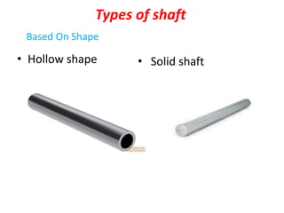
- 2. Types of shaft • Hollow shape • Solid shaft Based On Shape
- 3. Transmitting Shafts Line shaft :- It is use to transmit the power to several machine. Stub shaft :- When shaft is an integral part of the machine or engine is called stub shaft. Counter shaft :- A shaft that connect to prime mover to line of machine is called counter shaft. Based on Application
- 4. Machine Shaft :- When shaft is an integral part of the machine or engine is called machine shaft. Spindle shaft :- A short hollow shaft having application of transmitting the power to tool or a machine is called spindle shaft.
- 5. Based on Construction Rigid shaft :- It is a shaft which cannot be bend or deformed out of shape during transmission of rotary motion between two object or machine. Flexible shaft:- It is a shaft which is partially deformed in a manner not to affect the transmission of motion is known as flexible shaft.
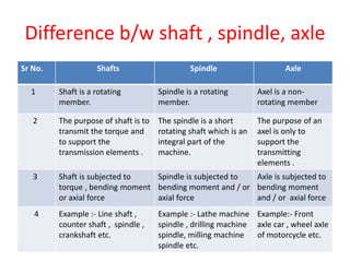
- 6. Difference b/w shaft , spindle, axle Sr No. Shafts Spindle Axle 1 Shaft is a rotating member. Spindle is a rotating member. Axel is a non- rotating member 2 The purpose of shaft is to transmit the torque and to support the transmission elements . The spindle is a short rotating shaft which is an integral part of the machine. The purpose of an axel is only to support the transmitting elements . 3 Shaft is subjected to torque , bending moment or axial force Spindle is subjected to bending moment and / or axial force Axle is subjected to bending moment and / or axial force 4 Example :- Line shaft , counter shaft , spindle , crankshaft etc. Example :- Lathe machine spindle , drilling machine spindle, milling machine spindle etc. Example:- Front axle car , wheel axle of motorcycle etc.
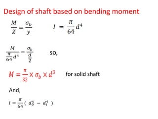
- 7. Design of shaft based on bending moment for solid shaft so, And,
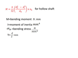
- 8. for hollow shaft M=bending moment I=moment of inertia =bending stress Y=
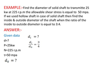
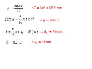
- 9. EXAMPLE:-Find the diameter of solid shaft to transmitte 25 kw at 225 r.p.m the allowable shear stress is equal to 50 mpa. If we used hollow shaft in case of solid shaft then find the inside & outside diameter of the shaft when the ratio of the inside to outside diameter is equal to 3:4. ANSWER:- Given data d=? P=25kw N=225 r.p.m τ=50 mpa
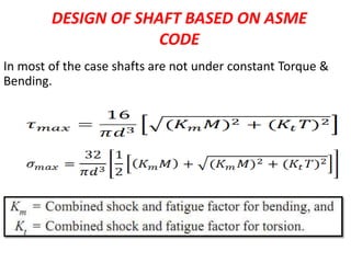
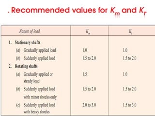
- 11. DESIGN OF SHAFT BASED ON ASME CODE In most of the case shafts are not under constant Torque & Bending.
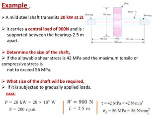
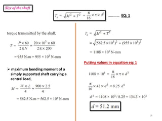
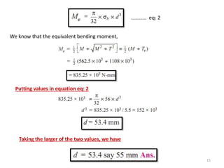
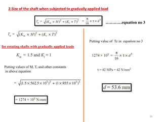
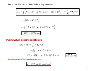
- 13. Example . A mild steel shaft transmits 20 kW at 200 rpm. It carries a central load of 900N and is simply supported between the bearings 2.5 m apart. Determine the size of the shaft, If the allowable shear stress is 42 MPa and the maximum tensile or compressive stress is not to exceed 56 MPa. What size of the shaft will be required, if it is subjected to gradually applied loads. DATA: 13
- 14. maximum bending moment of a simply supported shaft carrying a central load, Putting values in equation eq: 1 ………… EQ: 1 14
- 15. We know that the equivalent bending moment, ………… eq: 2 Putting values in equation eq: 2 Taking the larger of the two values, we have 15
- 16. 2.Size of the shaft when subjected to gradually applied load Putting values of M, T, and other constants in above equation Putting value of Te in equation no 3 …………equation no 3 for rotating shafts with gradually applied loads 16
- 17. We know that the equivalent bending moment, Putting values in above equation eq Taking the larger of the two values, we have 17
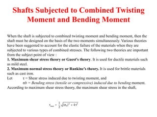
- 18. Shafts Subjected to Combined Twisting Moment and Bending Moment When the shaft is subjected to combined twisting moment and bending moment, then the shaft must be designed on the basis of the two moments simultaneously. Various theories have been suggested to account for the elastic failure of the materials when they are subjected to various types of combined stresses. The following two theories are important from the subject point of view : 1. Maximum shear stress theory or Guest's theory. It is used for ductile materials such as mild steel. 2. Maximum normal stress theory or Rankine’s theory. It is used for brittle materials such as cast iron. Let τ = Shear stress induced due to twisting moment, and σb = Bending stress (tensile or compressive) induced due to bending moment. According to maximum shear stress theory, the maximum shear stress in the shaft,
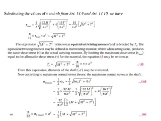
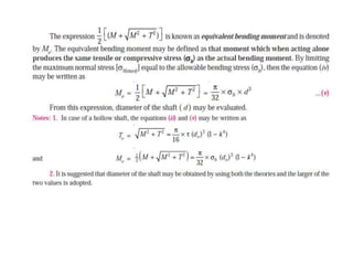
- 19. Substituting the values of τ and σb from Art. 14.9 and Art. 14.10, we have
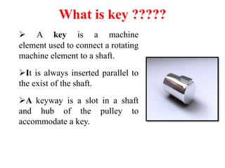
- 21. What is key ????? A key is a machine element used to connect a rotating machine element to a shaft. It is always inserted parallel to the exist of the shaft. A keyway is a slot in a shaft and hub of the pulley to accommodate a key.
- 22. Types of Keys
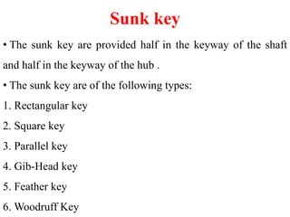
- 23. Sunk key • The sunk key are provided half in the keyway of the shaft and half in the keyway of the hub . • The sunk key are of the following types: 1. Rectangular key 2. Square key 3. Parallel key 4. Gib-Head key 5. Feather key 6. Woodruff Key
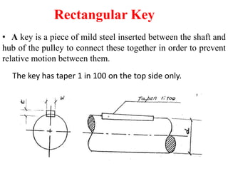
- 24. Rectangular Key • A key is a piece of mild steel inserted between the shaft and hub of the pulley to connect these together in order to prevent relative motion between them. The key has taper 1 in 100 on the top side only.
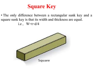
- 25. Square Key • The only difference between a rectangular sunk key and a square sunk key is that its width and thickness are equal. i.e , W=t=d/4
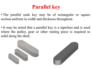
- 26. Parallel key • The parallel sunk key may be of rectangular or square section uniform in width and thickness throughout. • It may be noted that a parallel key is a taperless and is used where the pulley, gear or other mating piece is required to solid along the shaft.
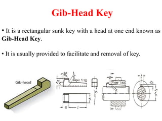
- 27. Gib-Head Key • It is a rectangular sunk key with a head at one end known as Gib-Head Key. • It is usually provided to facilitate and removal of key.
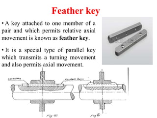
- 28. Feather key • A key attached to one member of a pair and which permits relative axial movement is known as feather key. • It is a special type of parallel key which transmits a turning movement and also permits axial movement.
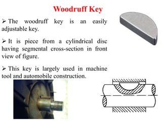
- 29. Woodruff Key The woodruff key is an easily adjustable key. It is piece from a cylindrical disc having segmental cross-section in front view of figure. This key is largely used in machine tool and automobile construction.
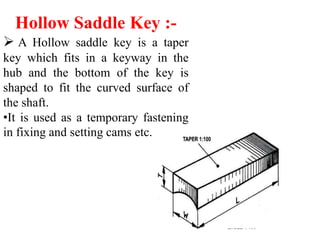
- 30. Hollow Saddle Key :- A Hollow saddle key is a taper key which fits in a keyway in the hub and the bottom of the key is shaped to fit the curved surface of the shaft. •It is used as a temporary fastening in fixing and setting cams etc.
- 31. Tangent Keys The tangent key are fitted in a pair at right angles. Each key is to withatand torsion in one direction only. sThey are used in large heavy duty shaft.
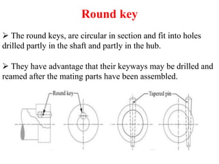
- 32. Round key The round keys, are circular in section and fit into holes drilled partly in the shaft and partly in the hub. They have advantage that their keyways may be drilled and reamed after the mating parts have been assembled.
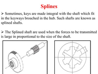
- 33. Splines Sometimes, keys are made integral with the shaft which fit in the keyways broached in the hub. Such shafts are known as splined shafts. The Splined shaft are used when the forces to be transmitted is large in proportional to the size of the shaft.


