Proceedings of 2005 Particle Accelerator Conference, Knoxville, Tennessee
COUPLER DESIGN FOR THE LCLS INJECTOR S-BAND STRUCTURES∗
Zenghai Li, Jose Chan, Lynn D. Bentson, David H. Dowell,
Cecile Limborg-Deprey, John F. Schmerge, David Schultz, Liling Xiao, SLAC, USA
Abstract
The LCLS injector is required to provide a 1-nC, 10ps bunch with a normalized rms transverse projected
emittance of less than 1 micron. The LCLS beam is
generated and accelerated in a 1.6-cell S-band RF gun at
120 MV/m up to 6 MeV. The gun is followed by two
SLAC 3-m S-band accelerator structures to further
accelerate the beam to 135 MeV which moves the beam
out of the space-charge dominated regime. In the SLAC
S-band structures, the RF power feed is through a single
coupling-hole (single-feed coupler) which results in a
field asymmetry. The time dependent multipole fields in
the coupler induce a transverse kick along the bunch and
cause the emittance to increase above the LCLS
specification. To meet the stringent emittance
requirements for the injector, the single-feed couplers will
be replaced by a dual-feed racetrack design to minimize
the multipole field effects. We will present detailed
studies of the multipole fields in the SLAC linac RF
coupler and the improvements with the dual-feed ractrack
design using the parallel finite element S-parameter solver
S3P.
INTRODUCTION
The electron beam in the LCLS[1] injector is
produced and accelerated to 6 MeV in a 1.6-cell S-band
photo RF gun[2]. Two SLAC 3-m S-band accelerator
structures operating at 19.5 and 25 MV/m gradient, are
used to accelerate the beam out of the space charge
dominated regime. In the SLAC S-band structure, the RF
power feed is through a single coupling hole. Time
dependent multipole fields in the coupler induce
transverse kicks along the bunch, causing head-tail beam
emittance degradation, which is important for the LCLS
injector beams because of the stringent emittance
requirement. In the results presented in ref[3], the
measured asymmetries in the SLAC structure coupler take
the form of a linear amplitude and phase variation across
the coupler cell as expressed in Eq.[1].
∆E x j ωt − kz +∆Φ 2 a
Ez = Ez 0 1 +
e
Ez 0 2 a
x
σ ∆px
(2)
+σ
ε n − final = ε
mc
For a dipole head-tail angle of 200 micro-radian, the
estimated RMS emittance increase is about 2%/12% with
an initial emittance of 1 micron and beam size of 1 mm
for the first and second linac sections respectively[5]. This
2%/12% emittance increase is not acceptable for the
LCLS beam so the dipole fields in the coupler must be
reduced. Compensating the head-tail kicks using
transverse wakefield would not be a satisfying solution
for all possible beam parameters. Since the dipole term is
mainly due to the phase asymmetry, a viable solution to
reduce the dipole head-tail effect is to replace the singlefeed coupler with a dual-feed design. In addition, a
racetrack cell profile will be needed to minimize the
quadrupole fields. In this paper, we will present the design
and analysis of the new dual-feed racetrack coupler for
the LCLS injector S-band structures.
2
2
n − initial
TOLERANCE ON MULTIPOLE FIELDS
As seen in equation 2, the normalized emittance
increase is independent of energy, but depends on the
square of the beam size and thus is typically most
important in the injector where the beam size is large.
Numerical studies on the tolerances on dipole and
quadrupole head-tail effects in the coupler cell of the
LCLS injector linacs have been performed using
PARMELA. In the PARMELA simulations, the head-tail
kicks were introduced at the entrance of the coupler cell
as a single kick. The dipole kick was represented by a
linear angle offset from head-to-tail and the quadrupole
kick was introduced as a linear quadrupole strength
varying from head-to-tail. For both cases, we looked at
the growth of the 80%-emittance (over 100 slices).
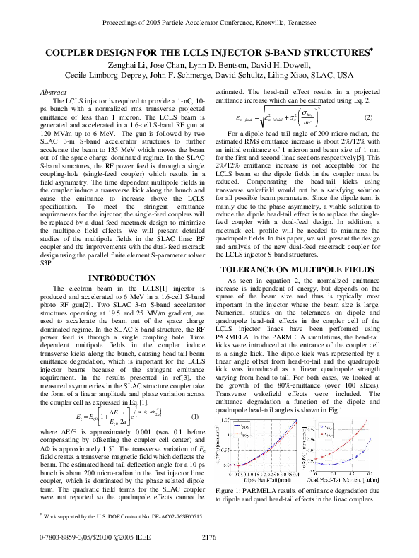
Transverse wakefield effects were included. The
emittance degradation a function of the dipole and
quadrupole head-tail angles is shown in Fig 1.
Figure 1: PARMELA results of emittance degradation due
to dipole and quad head-tail effects in the linac couplers.
Work supported by the U.S. DOE Contract No. DE-AC02-76SF00515.
0-7803-8859-3/05/$20.00 c 2005 IEEE
2
x
(1)
where ∆E/E is approximately 0.001 (was 0.1 before
compensating by offsetting the coupler cell center) and
∆Φ is approximately 1.5°. The transverse variation of Ez
field creates a transverse magnetic field which deflects the
beam. The estimated head-tail deflection angle for a 10-ps
bunch is about 200 micro-radian in the first injector linac
coupler, which is dominated by the phase related dipole
term. The quadratic field terms for the SLAC coupler
were not reported so the quadrupole effects cannot be
∗
estimated. The head-tail effect results in a projected
emittance increase which can be estimated using Eq. 2.
2176
�Proceedings of 2005 Particle Accelerator Conference, Knoxville, Tennessee
The tolerance on the kick is set by limiting the
emittance growth to 2%. For the dipole kick, the angle
difference should not be larger than 120 micro-radian
from head-to-tail of a 10-ps bunch as illustrated in Fig. 1.
For the quadrupole kick, the quadrupole moment should
not exceed 0.1 rad/m from head-to-tail of a 10 ps bunch.
Allowing the possibility to operate with 20 ps long pulses,
the actual tolerances are 60 micro-radian for the dipole
and 0.05 rad/m for the quadrupole. Based on the
analytical estimations, the dipole deflection in the coupler
must be reduced by at least a factor of 4 below the
existing value in order to reduce the emittance growth to
acceptable levels.
MULTIPOLE ANALYSIS
The parallel finite element S-parameter code S3P[4]
is used to calculate the coupler matching and the full 3-D
RF fields in the coupler. The impact of the coupler fields
on the beam dynamics is studied by analyzing the particle
momentum change after traversing the coupler fields. The
equation of motion
v
v v
d (γβ )
e v
=
( E + cβ × B )
(3)
dt
m0 c
is integrated through the coupler field. The transverse
momentum change, ∆(γβ), is Fourier decomposed into
multipole
to the following equation
v terms according
v
v
v
v
∆ (γβ ⊥ ) = A0 ( xx0 + yy0 ) + Dx x0 + Dy y0
v
v
v
v
+Q( yy0 − xx0 ) + S ( yx0 + xy0 )
(4)
where A0 is the RF focusing, Dx/Dy, Q and S are the
dipole, quadrupole and skew quadrupole components
respectively.
phase of a 10 degree long bunch. Table 1 lists the headtail momentum (∆(γβ⊥)) and steering angle (∆(γβ⊥)/γ) for
a bunch accelerated -10 degrees off crest.
Figure 3: Head-tail effect of SLAC 3-m structure: left)
dipole field; right) quadrupole field. The thicker line
segment represents the 10 degree bunch.
Table 1: Dipole and quadrupole head-tail effects in the
SLAC 3-m structure input/output couplers.
Beam energy (g)
Dipole: ∆(γβ⊥)
Quad: D(gβ^)/m
Dipole head-tail angle (rad)
Quad head-tail angle (rad/m)
Input
10
2.6×10⁻³
7.8×10⁻¹
2.6×10⁻⁴
7.8×10⁻²
Output
130
1.0×10⁻³
4.4×10⁻¹
7.7×10⁻⁶
3.4×10⁻³
Numerical results have shown that both the dipole
and quadrupole head-tail effects in the input couplers of
both injector linacs are larger than the tolerance set by the
emittance criteria. In the output coupler, the head-tail
effects are about 4 times smaller than in the input coupler
and found to be acceptable. Thus only the input couplers
need to be replaced by a more symmetric design.
DUAL-FEED INPUT COUPLER
The dual-feed scheme includes a power distribution
waveguide system and a dual-feed coupler, as shown in
Fig. 4. The design approach of such a system is to use as
much standard parts as possible to save cost. With this in
mind, the coupler port dimension in the new design is
increased to the full dimension of the WR284 waveguide.
The tapers are eliminated and standard WR284 flanges
can be used. The power splitter is a simple WR284 “T”
and the 180 degree waveguide bend can be made by
bending the standard WR284 waveguide.
SINGLE-FEED SLAC STRUCTURE
Figure 2: Symmetric single-feed coupler model used in
S3P simulation.
In the S3P simulations, a two-port network is
required to calculate the S-parameters and the traveling
wave fields. Back-to-back symmetric models as shown in
Fig. 2 were built for the input and output couplers
respectively. The 3D traveling RF fields in the coupler
models were obtained by driving “port-1” with a TE10
mode. In the beam dynamics studies only the field in the
“port-1” side is used for the input coupler and only the
field in the “port-2” side is used for the output coupler.
The transverse dipole and quadrupole moments of the
coupler fields, at a gradient of 20 MV/m, as functions of
beam RF phase, where zero phase is the RF crest, are
plotted in Fig. 3. The thick line segments indicate the RF
Figure 4: Dual-feed waveguide system. The coupler port
dimensions are the same as the WR284 waveguide to
simplify the system.
Dual-feed coupler optimization
The dual-feed coupler eliminates both geometric and
phase related dipole fields by symmetry. The design
focuses upon matching the coupler and minimizing the
quadrupole term using a racetrack cell. A sketch of the
2177
0-7803-8859-3/05/$20.00 c 2005 IEEE
�Proceedings of 2005 Particle Accelerator Conference, Knoxville, Tennessee
dual-feed racetrack coupler is shown in Fig. 5. The left
figure shows the racetrack profile of the coupler cell. The
two (+) symbols indicate the centers of two racetrack arcs.
The separation of the two arc centers is optimized to
reduce the quadrupole field. The edges of the coupling
irises are rounded to minimize possible field enhancement
and RF heating. The left figure shows the coupler cell
with the length of the full WR284 height, which is about
5-mm longer than a regular 2π/3 cell. The design was
done iteratively by adjusting the arc separation to
minimize quadrupole fields and adjusting the iris opening
and the arc radius to match the coupling. After a number
of iterations, a factor of 10 reduction in quadrupole field
and a less than 0.02 reflection were achieved. The phase
dependent quadrupole field in the present dual-feed
racetrack design is shown in Fig 6 to compare with the
original single-feed design and the dual-feed design with
the cylindrical cell. The head-tail kick angles for a 10
degree bunch are shown in Table 2. The dual feed with
racetrack design is approximately 20 times smaller than
the single feed case because the peak quadrupole term is
smaller and the curve is flat at the desired operating
phase. The design is about an order of magnitude better
than the tolerance level.
Figure 5: Dual-feed coupler with racetrack cell profile to
minimize dipole and quadrupole fields.
size; c) RF feed amplitude; and d) RF feed phase. As an
analogy to Eq.1, the fields in a dual-feed coupler cell can
be expressed as the following:
Ez =
Ez 0
N
∑V
2
Vi Di
i =1 0 D0
i
∆E
x
y j Φ 0 + D0 ∆Φ sin θi 2 a +cosθi 2 a
+ cos θ i
(5)
1 +
sin θi
e
2a
2a
Ez 0
D
x
y
where V0 is the amplitude necessary to produce an
accelerating gradient Ez0 and D0 is the nominal dimension
of the coupler iris. Vi, Di and θi are the complex
amplitude, coupling iris dimension and coupling iris
angular position of the ith coupler respectively. The
criteria used for acceptable tolerance were that the dual
feed dipole term in Eq. 5 must be reduced by a factor of
100 from a single feed structure, and the quadrupole term
must be reduced by a factor of 10. Table 3 lists the error
and the corresponding tolerance as well as the criteria
setting the tolerance for the four errors described above.
Table 3: The tolerance for the four coupler errors.
Error
Coupler Position
Coupler Iris Size
RF Feed Amplitude
RF Feed Phase
Tolerance
∆θ < 1.1°
∆D/D0 < .02
∆V/V0 < .02
∆α < 1.1°
Defining Criteria
Dipole
Dipole
Dipole
Dipole
All errors were considered independently. Thus
multiple simultaneous errors will produce larger dipole
and quadrupole terms than desired. However, the coupler
position tolerance is quite loose. The coupler iris size is
also relatively loose. The RF amplitude tolerance will be
challenging but in principle can be reached by tuning the
RF power splitter. The RF phase error can in principle be
set to 1° by measurement and waveguide phase tuning so
phase errors do not appear to be problematic.
SUMMARY
Figure 6 Quadrupole moments in the dual-feed racetrack
coupler. The quadrupole moments in the single-feed and
the cylindrical dual-feed are shown for comparison.
Table 2: Comparison of quadrupole kick angles
Input coupler: comparison of quad head-tail
∆(γβ⊥)/m: 10 Degree bunch
∆(γβ⊥)/m HT angle ∆q (rad/m)
Single feed
0.78
0.078
Symmetric dual
0.63
0.063
Race-track dual
0.04
0.004
REFERENCE
Dimension Tolerance on Field Asymmetry
Machine/construction errors and RF feed imbalance
of the dual-feed coupler will result in field asymmetry in
the coupler cell. We consider the effects of four errors: a)
Coupler position (not 180 degrees apart); b) Coupler iris
0-7803-8859-3/05/$20.00 c 2005 IEEE
The multipole fields in the single-feed SLAC S-band
structure are analyzed and found to be larger than the
acceptable level for the LCLS injector accelerator
sections. A dual-feed racetrack coupler has been designed
to replace the single-feed input coupler. The new design
eliminated the dipole fields by symmetry and reduced the
quadrupole field by a factor of 10. The tolerance on the
dual-feed geometry and RF errors were analyzed and
found to be achievable. The mechanical design for the
new coupler is in progress.
[1] http://www-ssrl.slac.stanford.edu/lcls
[2] Liling Xiao, et al, “Dual-feed RF Gun Design for
LCLS,” this proceedings.
[3] The Stanford Two-Mile Accelerator, Edited by R.B.
Neal, 1968, W.A. Benjamin Inc, pg 146.
[4] L. Lee, et al., “Solving Large Sparse Linear Systems
in End-to-end Accelerator Structure Simulations,”
Proceedings of the 18th International Parallel and
Distributed Processing Symposium, 2004.
[5] C.Limborg-Deprey et al. “RF Modifications in the
LCLS Injector Beamline,” this proceedings.
2178
�