Academia.edu no longer supports Internet Explorer.
To browse Academia.edu and the wider internet faster and more securely, please take a few seconds to upgrade your browser.
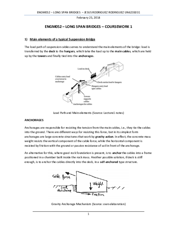
ENGM052 – LONG SPAN BRIDGES – COURSEWORK 1 1) Main elements of a typical Suspension Bridge
ENGM052 – LONG SPAN BRIDGES – COURSEWORK 1 1) Main elements of a typical Suspension Bridge
 Jesús Rodríguez Rodríguez
Related Papers
Structural Efficiency of Steel Stiffening Deck Systems in Suspension Bridges Due to Gravity Loads
Structural Efficiency of Steel Stiffening Deck Systems in Suspension Bridges Due to Gravity Loads2020 •
In this paper, suspended stiffened decks in suspension bridges are considered. Three steel deck-stiffening systems are compared structurally; the plate girder, the box girder and the stiffening truss. A three-span continuous suspension bridge model is considered. Analysis is made by the second order non-linear deflection theory in its linearized form. Developed software is used for the analysis to determine the induced tension in the cable, moments, shears and deflections of the girders for any general live load case. AASHTO criteria for steel girders are adopted. AASHTO highway live loads-HL 93-are applied to Khartoum-Tuti Suspension Bridge in Khartoum, Sudan for each type of the stiffening systems. Ten load cases are considered and discussed. Results have shown that the most efficient type to resist gravity loads is the stiffening truss, followed by the box girder and last is the plate girder.
This paper reports the results of a piece of research about long-span suspension bridges with multiple-box girder steel deck characterized by low drag coefficient and high aeroelastic stability. For this type of bridges, by increasing the span length, the contribution to the stiffness of the suspension cables becomes dominant with respect to that of the deck, so that the ratio of the frequency of the first torsional mode to the frequency of the first vertical bending mode approaches unity, while they both decrease. As a consequence, if the deck cross-section geometry does not allow single-degree-of-freedom torsional flutter, one would observe the onset of two-degree-of-freedom classical flutter at a relatively low wind speed, depending on the dynamic and aerodynamic properties of the structure. The research presented herein, proposes an innovative approach to the design of long-span suspension bridges by studying deck configurations with frequency ratios of first torsional to vertic...
Scenario You are a graduate structural engineer working for a major consultancy company that is an acknowledged world-leader in its field. The company employs 6000 staff and operates from 70 offices in 40 countries throughout the world and has an annual turnover of some £500 million per year. You are working within a team of specialist bridge design engineers who are responsible for a large portfolio of bridges being designed for construction in the UK and in a number of overseas developing countries. You have been given the task of designing a steel bridge to carry a railway across a major motorway in the South of England. The form of the bridge will be a triangulated pin-jointed steel truss (see photo 4 below) – this has been determined to be the most appropriate form of bridge chosen from the many different types of bridge structure used throughout the world. As part of the initial design process you are required to analyse the proposed bridge and determine the forces within each of the bridge members. The calculation of these forces will subsequently lead to the selection of the most appropriate size of steel section for the members and the detailed design of the connections where the members meet. In this exercise the learner will apply techniques for the solution of simultaneous equations using methods, including matrix techniques, that form the basis of the calculations that would be undertaken by the structural engineer, often now a days carried out using powerful computer software packages. Importance of Exemplar in Real Life Bridges range from small structures such as simple footbridges to iconic structures such as the Humber Bridge which, when opened in 1981, held a 17 year world record for being the longest single span suspension bridge in the world. Built at a cost in excess of £150m its world record and cost of construction have since been far exceeded – the record for the longest span suspension bridge currently being the Akashi-Kaikyō Bridge in Japan which has a suspended centre span of nearly 2000 metres, although such records are being continuously broken. Although the construction of such iconic bridges is often a statement of national pride the decision to construct any bridge is usually based on social and economic criteria. For example, the construction of the Humber Bridge provided access to two areas of the UK which were geographically remote and provided the opportunity for commercial, industrial and tourist development and saved many millions of vehicle miles in providing a short transit route between both sides of the Humber estuary. Such potential developments and financial savings are the justification for the huge cost investments made in building bridges throughout the world although factored into such cost considerations has to be the ongoing cost of maintenance and repair over the life span of the bridge. Bridges are constructed in a wide range of materials including masonry, timber, steel, reinforced concrete, prestressed concrete and composite construction. They are built in a variety of different forms including simple beams, trusses, arches, suspension, and cable-stayed structures. The choice of material and structural form depends on a wide range of factors such as the load to be carried including the weight of vehicles, the span length of the bridge, the construction and maintenance costs, the visual impact and so on. Whatever the final choice the Structural Engineer makes, either individually or as part of a design team has an important role to play in ensuring the most appropriate choice of structure and materials and in ensuring the structural integrity of the bridge during construction and throughout its working life. Examples of different types of bridges can be seen in figures 1 to 4. Figure 4 illustrates the type of bridge that we will be considering in this exercise. It is fabricated from structural steel sections to form a bridge which is simply supported i.e resting and supported on a supporting structure at either end.-1
NIŠ AND BYZANTIUM: TWENTY SECOND INTERNATIONAL SYMPOSIUM NIŠ, 3 – 5 JUNE 2023 THE COLLECTION OF SCIENTIFIC WORKS XXII, ed. M. Rakocija
Staging Imperial Aspirations: Spolia At Ljuboten And The Symbolic Role Of Antiquity, 257-2732024 •
RELATED PAPERS
Fruit, Vegetable and Cereal Science and Biotechnology
An International Organization to Improve Knowledge on Potato Virus YOrthodoxy in Ukraine: Collection of articles Православ’я в Україні: Збір-ник статей
Богоявленський собор Києво-Братського монастиря2023 •
2024 •
ÜSKÜP'TE MEDDAH MEDRESESİ
MEDDÂH MEDRESESİ’NİN ŞÂİR ÂLİMİ FETTÂH EFENDİ’NİN ŞİİRLERİNDE HAZRET-İ MUHAMMED2024 •
Forensic Science International
Value of histological study in the fronto-sphenoidal suture for the age estimation at the time of deathJournal of Clinical and Analytical Medicine
Psöriatik Artritli Bir Hastada İnfliksimab Tedavisi Sırasında Gelişen Guillain-Barre Sendromu: Olgu Sunumu2016 •
2017 •
Applied Physics A
A structural approach in the study of bones: fossil and burnt bones at nanosize scale2016 •
Biofarmasi Journal of Natural Product Biochemistry
Effect of garlic (Allium sativum) extract on reduction of total cholesterol and HDL cholesterol ratio in hypercholesterolemic rats2008 •
2020 •