
Abstract
This study introduces a three-dimensional numerical analysis of the mixing yield stress fluid inside stirred vessels. The Bingham–Papanastasiou model predicts the yield stress behavior of the working fluid. The implications of a new anchor impeller design are investigated; it involves certain modifications to a typical anchor impeller’s blade. Different curved shapes replace the straight blade of a classical anchor. The flow pattern and energy consumed inside the stirred system for various geometrical configurations, Reynolds numbers (0.1, 1, 10, and 100), and Bingham numbers (1, 10, 100, and 500) have been investigated. According to the findings, introducing this new geometrical configuration gives a significant acceleration of flow pattern and extension of the well-mixed zone, as well as decreased power consumption (
Nomenclature
-
-
surface around the impeller (
-
-
Bingham number
-
-
container diameter (
-
-
anchor impeller diameter (
-
-
shaft diameter (
-
-
x-Force path (
-
-
y-Force path (
-
-
container height (
-
-
stress growth parameter (
-
-
impeller rotational speed, (
-
-
Power number
-
-
vessel radius (
-
-
Reynolds quantity
-
-
rate of deformational tensor
-
-
nondimensional velocity (
-
-
blade thickness (
Greek symbols
-
-
shear rate (
-
-
dynamic viscosity (
- Ca
-
curvature angle (° degree)
-
-
torque (Nm)
-
-
fluid density (
-
-
shear stress (
-
-
impeller rotational rapidity (
1 Introduction
Mechanical agitation is one of the fundamental unit operations widely used in the industrial fields of chemical, pharmaceutical, metallurgy, petroleum, gas dispersion, etc. The operation of mechanical agitation essentially contributes to increasing the homogeneity degree of the mixture and accelerates the heat and mass transfer in the mixing system for obtaining a high final quality product with the required physicochemical characteristics.
Viscoplastic fluids are the most important kind of non-Newtonian fluid because they are characterized by high viscosity and complex rheological behavior. The mixing of these fluids produces many problems, such as the creation of a well-mixed region and a stagnant zone near the anchor blade [1]. Viscoplastic or yield stress fluids are substances that exhibit unique characteristics. Below a certain yield stress threshold, these substances behave like highly viscous liquids. However, once the yield stress is surpassed, they transform into shear-thinning liquids. Another term used to describe these materials is shear-thinning liquids.
When subjected to yield stress, these substances undergo a significant reduction in viscosity. This phenomenon is often observed, indicating a change in their flow behavior. The mechanical response of solids that involves time-dependent and irreversible (inelastic) stresses is referred to as viscoplasticity. In the industrial sector, heavy oils, slurries of mining tailings, freshly mixed concrete, and wood pulp are notable examples of viscoplastic materials. Likewise, in ecological contexts, cooled lava and mud also exhibit viscoplastic properties. Measuring rheological properties involves the characterization and quantification of how materials respond to applied forces or deformations. The most widely used method to measure rheological properties is rotational viscometry. This method measures the viscosity of fluids by rotating a spindle or bob in the sample and measuring the torque required for rotation. The resulting shear stress and shear rate are used to determine the viscosity.
Many researchers investigated the performance of different agitator designs inside the stirred tank system and analyzed their impact on the hydrodynamics parameters such as flow pattern, energy consumed, and heat transfer. The anchor impeller is one of the most important agitators for mixing highly viscous fluids. Several studies focused on the geometry modification of anchor impellers and their effect on mixing efficiency. Hami et al. [2] and Rahmani et al. [3] managed a thermo-hydrodynamic study of combining Newtonian fluids inside a cylindrical container. They investigated the mixing parameters with an inclined anchor impeller blade. The results revealed that an anchor with no inclination consumes significantly more energy. The effect of anchor impeller speed on eliminating the stagnant region for yield stress fluids in the stirred container has been studied widely [4,5,6]. Mebarki et al. [7] numerically investigated the mechanical agitation of viscoplastic fluids in stirred vessels with circular anchor impellers. They discussed the impact of the impeller design on the rheological parameters of the stirred tank (flow pattern behavior and power consumption). Ameur [8] has made a novel modification to the standard anchor impeller to improve fluid flow movement inside the stirred tank by adding arm blades to the standard impeller design. An improvement in the flow pattern has been noted, as has the elimination of the dead zone. According to the findings, the anchor with four blades is sufficient to obtain the best performance. Kazemzadeh et al. [9] and Ameur and Ghenaim [10] introduced a new agitator design in the mixing system: a curved blade turbine mounted on the classical anchor impeller. They investigated the effect of the combined anchor–turbine agitator on the flowing pattern, shearing zone, and power consumption. Kamla et al. [11] performed a numerical study of stirred tanks with modifications to the anchor impeller geometry for different Reynolds numbers (0.1–60). They found that the anchor with a circular shape is characterized by the lowest energy consumed. The arrangement with an octagonal form (A-8b), on the other hand, is distinguished by the widest well-sheared zone inside the container. Kada et al. [12] elaborated on the effect of the new modifications on the anchor impeller by including an arm blade to the standard anchor impeller shape and varying its inclination with different angles (20°, 45°, and 60°). The results obtained revealed that the most efficient impeller is the configuration of an anchor impeller with four arm blades inclined by 60°. This case enhanced the shearing zone in the container and reduced the energy consumed. A comparative study between the standard anchor impeller and the helical agitator was conducted by Yusof et al. [13]. From the result, they found that the anchor produces 0.28 Nm and the helical 0.24 Nm of torque during the mixing operation. Driss et al. [14] numerically investigated the mixing of viscous fluid by introducing a new design of anchor impeller in which pitched blades were mounted on the classical anchor impeller. They confirmed their numerical results with the previous experimental work [15,16,17,18]. These studies involve a two-dimensional numerical study of the thermal behavior of a yield stress fluid inside a stirred tank by an anchor impeller agitator. They discussed the thermal characteristics of the mixing system, including the temperature contour and isotherm line distribution. The results showed that the decrease in Bingham numbers (plasticity of fluid) improved heat transfer inside the stirred container. Some modifications were made to the anchor impeller shape, and they analyzed the influence of design on the structure of the flow pattern (velocities – shearing zone) and power consumption inside the stirred container [19,20,21,22,23,24,25]. Rahmani et al. [21] performed a comparative study between gate impellers, two-blade agitators, and anchor impeller agitators. They found that the anchor impeller is more efficient in accelerating fluid flow and minimizes power consumption during the mixing operation. Prajabpati and Ein-Muzaffar [26] performed a numerical study of the mixing of Xanthan gum solution inside a stirred tank. They obtained that the optimum value of clearance to diameter ratio is
Many research investigations have concentrated on yield stress fluids; however, a few studies have focused on the Bingham–Papanastasiou model. This study focuses on examining the impact of a novel anchor impeller design on the mixing characteristics and hydrodynamic behavior (including flow pattern, power consumption, and pumping capacity). The objective is to investigate these effects through numerical simulations. The innovative design involves replacing the conventional straight blades with wavy blades, aimed at enhancing the flow pattern within the mixing system. The simulations incorporate the Bingham–Papanastasiou model to accurately capture the behavior of the flow.
2 Geometric description
Figure 1 illustrates the geometry parameters of the mixing structure. It involves a cylindrical container with a flat surface bottom. The stirring is ensured by introducing a new design of anchor impeller (curved anchor blade) with different geometrical configurations. In this study, six different design instances were evaluated, as displayed in Figure 2. The details of the geometrical factors are shown in Table 1.
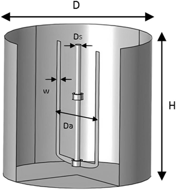
Mixing system geometry.
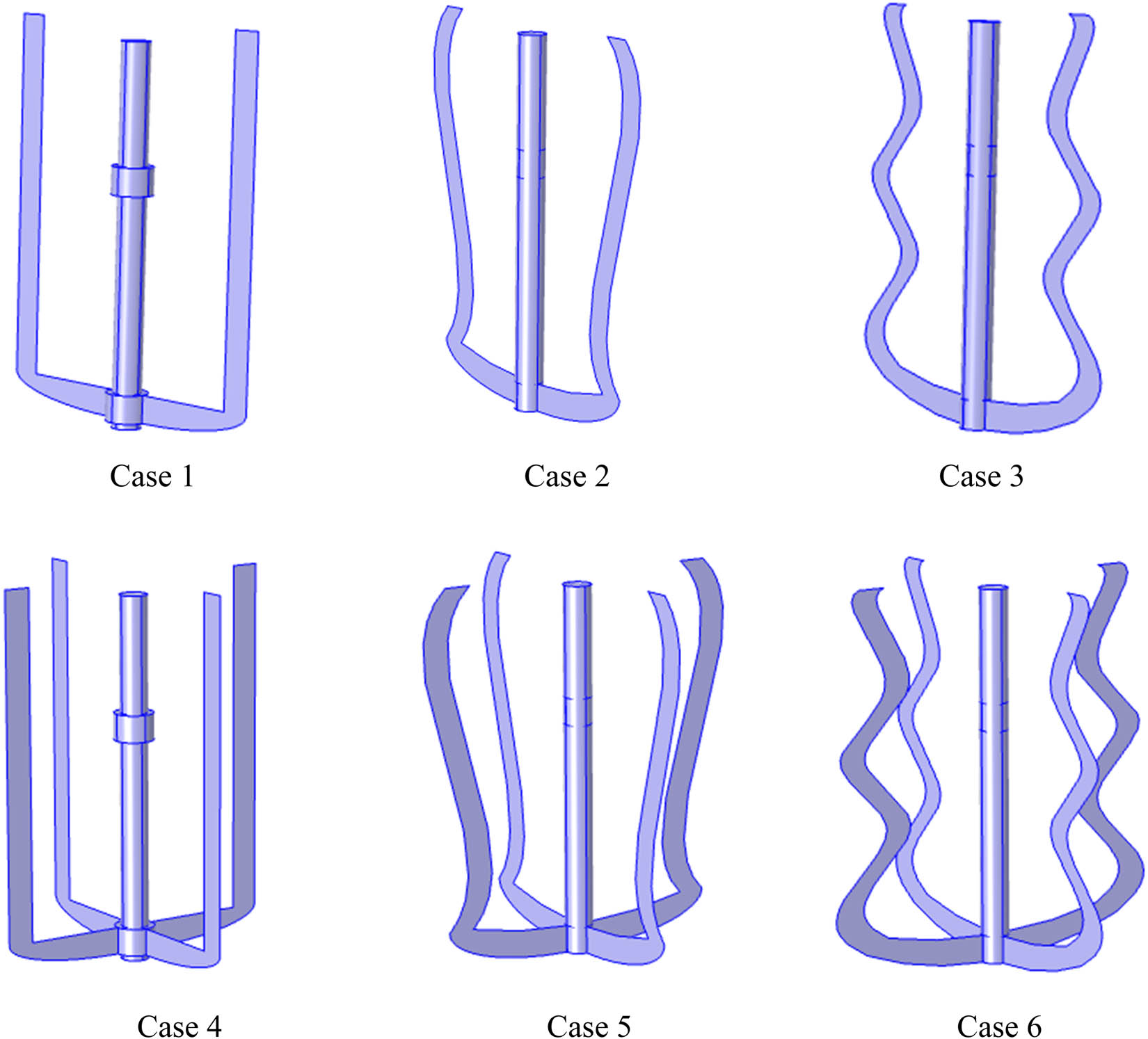
Anchor impeller with different modification shapes.
Measurements on the stirred tank geometry
|
|
|
|
|
|
|
Ca |
|---|---|---|---|---|---|---|
| 0.3 | 0.3 | 0.2 | 0.02 | 0.032 | 0.03 | 25° |
3 Mathematical model
The three-dimensional laminar flow of viscoplastic fluids (Bingham–Papanastasiou model) in a cylindrical container has been accomplished by using a computational fluid dynamics software package (COMSOL Multiphysics 5.4) and introducing different shapes of anchor impellers. The dimensionless equations are resolved by using the finite element methodology using Galarkin’s method. The computational domain is discretized with an unstructured grid (tetrahedral mesh), as shown in Figure 3. The residual convergence was set at 10−6 for this simulation.
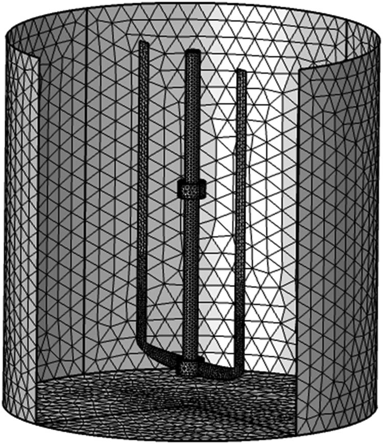
Mesh of the geometry study.
In this study, 3-D steady-state incompressible fluid flow has been assumed, and the dimensional governing formulas can be composed as shown in Sections 3.1 and 3.2.
3.1 Continuity equation
3.2 Momentum equation
According to the Bingham–Papanastasiou concept [27], the relationship that follows may be used to characterize the yield stress fluid:
where
3.3 Nondimensional variables
By using the above dimensionless parameters, Eqs (1)–(4) can be composed in a nondimensional structure, as shown in Sections 3.4 and 3.5.
3.4 Continuity equation
3.5 Momentum equation
The Papanastasiou-model equation in its dimensionless form is represented by the following expression:
where
where
where
Finally, the power consumption is calculated using the following equation:
Reynolds number is one of the parameters that describe the hydrodynamic flow in the mixing system. It is expressed as a ratio across the viscous powers and the inertial force:
The yield stress flow or fluid plasticity parameter of the yield stress fluid is defined by Bingham number in dimensionless form as follows:
4 Validation
It is vital to compare the results of our numerical research with the results that were previously published in the literature in order to verify the correctness of our numerical study’s findings. For the purpose of validation in this inquiry, the study of Marouche et al. [28] has been used for comparison. The Bingham modeling liquids utilized rheological and geometric features (a standard anchor impeller and a fluid with the characterization of
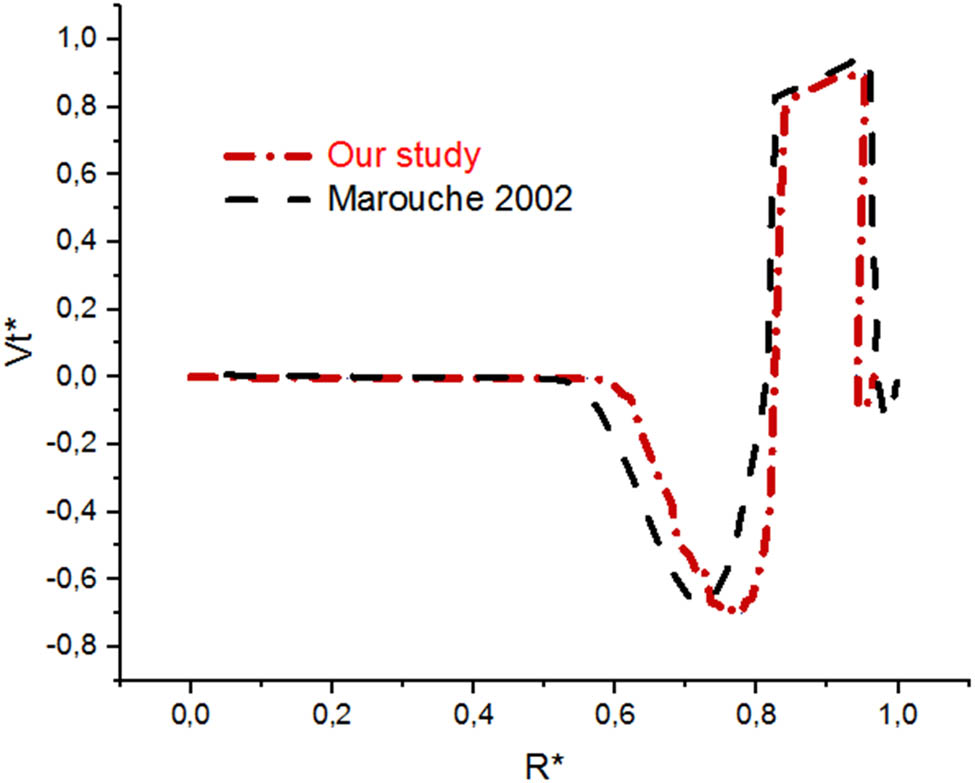
Tangential velocity in the tank.
5 Grid independence
In order to ensure the integrity and reliability of the results obtained from the code, it is crucial to verify their independence from variations in the grid structure or the number of elements. To validate this, extensive testing was conducted using multiple meshes, as shown in Table 2. In the 3D study, mesh element number 2,095,841 (fin mesh) was chosen so that there would be no change in the calculated values and the error in those values should be less than 10−6. The mesh test is carried out using the parameters
A test of the independence of the mesh
| Mesh type | Mesh number |
|
CPU time |
|---|---|---|---|
| Normal | 275,258 | 367.458 | 4 h 58 min |
| Fine | 1,144,853 | 367.501 | 9 h 09 min |
| Finer | 2,095,841 | 367.502 | 13 h 2 min |
| Extra mesh | 3,540,058 | 367.502 | 25 h 21 min |
6 Results and discussion
6.1 Inertia influence
The flowing configuration is the most important parameter that indicates the hydrodynamic structure inside the stirred container system. In this study, the flow pattern structure has been investigated under the influence of various inertia values (
Figure 5 gives the velocity distribution on the horizontal sector at the middle-high of the container with different Reynolds values (
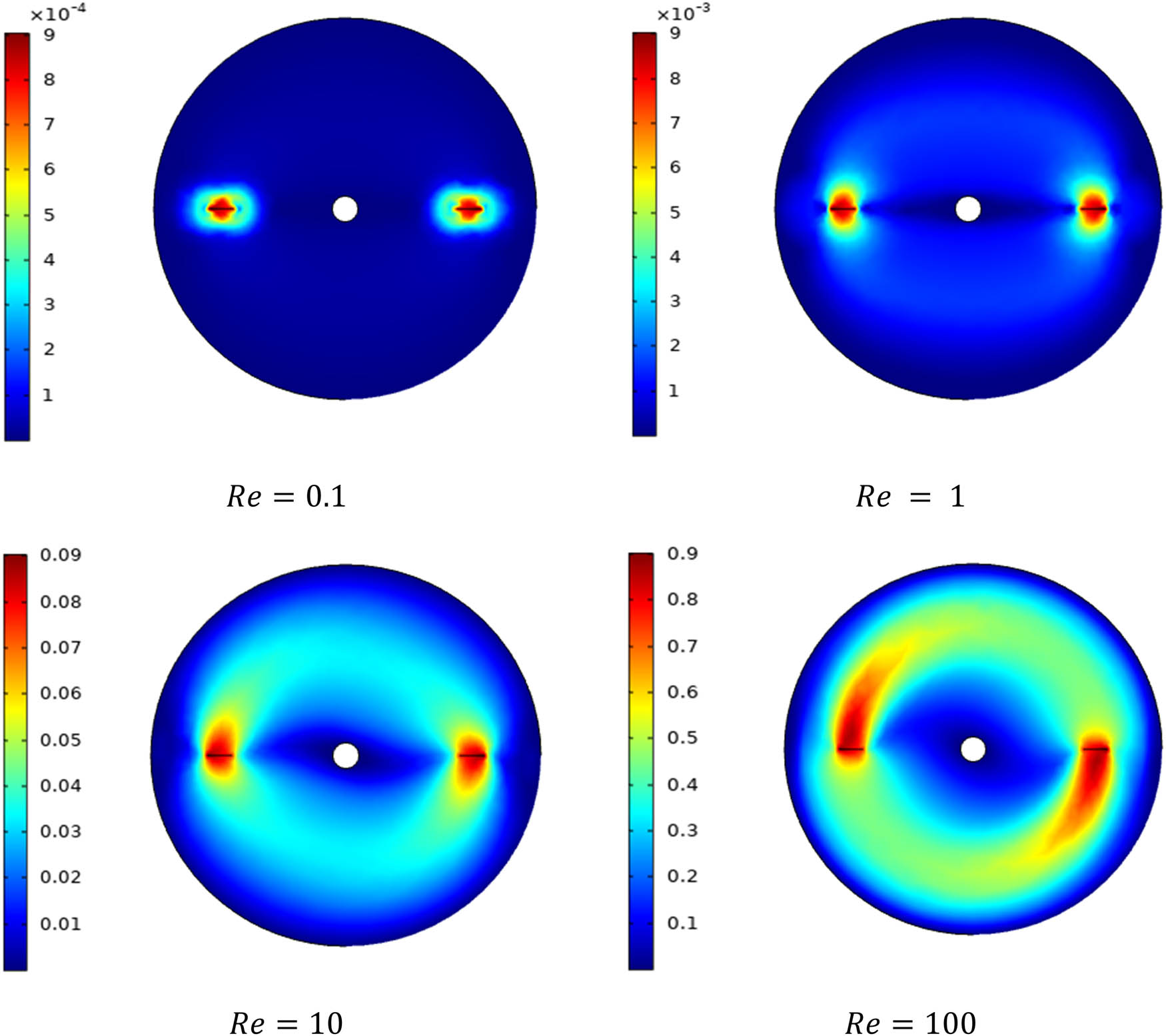
Velocity distribution on the horizontal sector mid-high of the container.
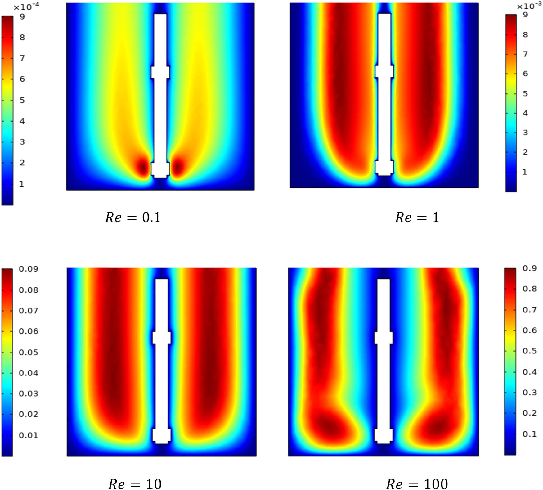
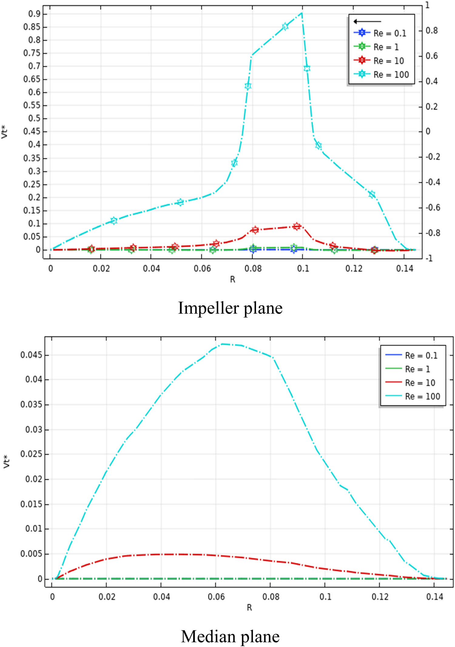
Velocity outline on the vertical sector of the container; impeller plane; and median plane.
Figure 7 presents the velocity in two directions of the impeller (median plane and impeller plane) with a comparison between the velocities in the two directions of the impeller. The maximum value of velocity in the impeller and median plane is 0.045 and 0.9, respectively. We also note that the flow is mainly tangential in the stirred tank. The same results were noted by Ameur [8] and Kada et al. [12] who found the dominance of tangential flows in the stirred system with an anchor impeller.
Tangential velocity
The flow patterns in a stirred vessel are shown through the distribution of the streamline presented in Figure 8 at the low Reynolds value (
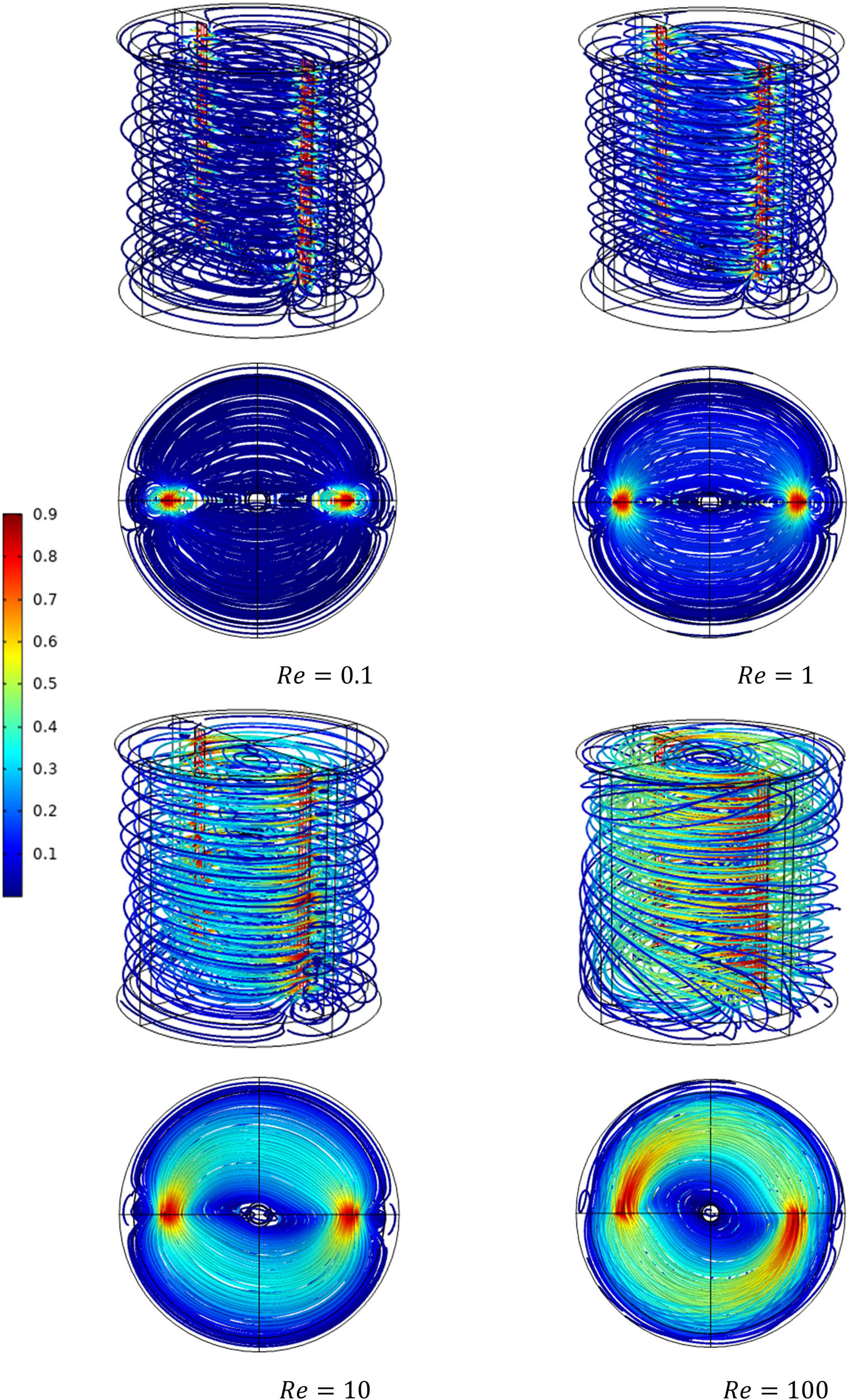
Streamline distribution in the whole vessel for diverse Reynolds quantities.
Figure 9 illustrates the variation of power consumption versus the Reynolds number. At low Reynolds number values, the stirred system consumes a significant amount of energy. Conversely, as the Reynolds value increases during the mixing operation, the energy consumption decreases significantly. This confirms the previous results of Mebarki et al. [7], Ameur [8], and Kada et al. [12]. The inertia has a big influence on changing the structure of the flowing design inside the stirred tank.
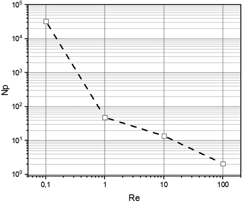
Power consumption as a function of Reynolds number.
6.2 Effect of design
To enhance the mixing circulation in the tank, we introduce a new design of classical anchor impellers in the stirred system. Many geometrical configurations were tested to analyze the hydrodynamics structure of the mixing system by introducing new geometrical configurations of anchor impellers.
Figures 10 and 11 present the velocity contour inside the stirred tank for diverse anchor geometries along the vertical and horizontal sections, respectively. It is noteworthy that the inclusion of curved blades in the design intensifies fluid pumping and, consequently, enhances circulation throughout the entire volume of the tank when compared to standard anchor blades. The geometric configuration of the wavy blades allows for a larger volume to be swept, resulting in a wider region of well-stirred fluid.
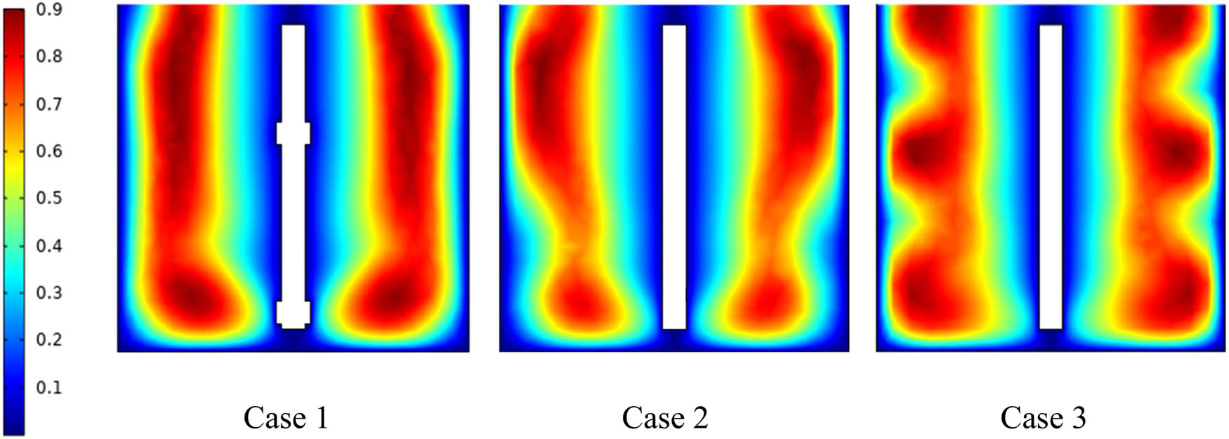
Velocity distribution in the vertical section of the vessel for different impeller designs (
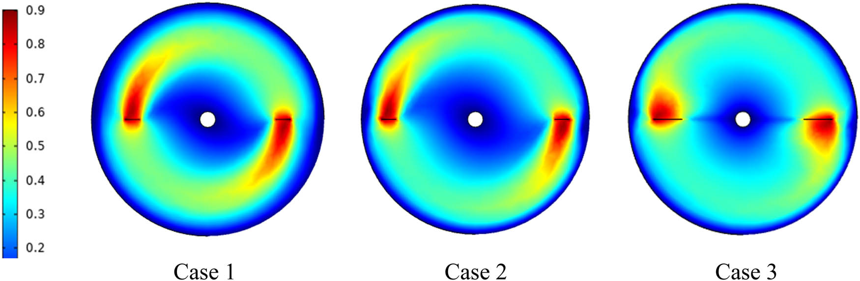
Velocity distribution in the horizontal section of the vessel for different impeller designs (
Figure 12 illustrates the streamline outline inside the stirred tank for diverse designs of impellers. In the first case, the streamlines exhibit remarkable similarity along the vessel, indicating the dominance of tangential flows due to the implementation of the classical anchor impeller. This observation shows a stagnation of fluid flow within the vessel under these conditions. However, in the second and third cases, a significant alteration in the fluid flow structure is observed. There is a noticeable transition of streamlined direction from horizontal to axial orientations, indicating the creation of an axial flow within the stirred tank. This axial flow pattern enhances the circulation of fluid within the mixing system. An increase in the velocity and improvement in the mixing operation by expanding the well-moving zone inside the stirred tank can be seen. Especially with Case 3, we found that it has an important effect on improving the flow pattern, in addition to reducing the power consumption during the mixing process.
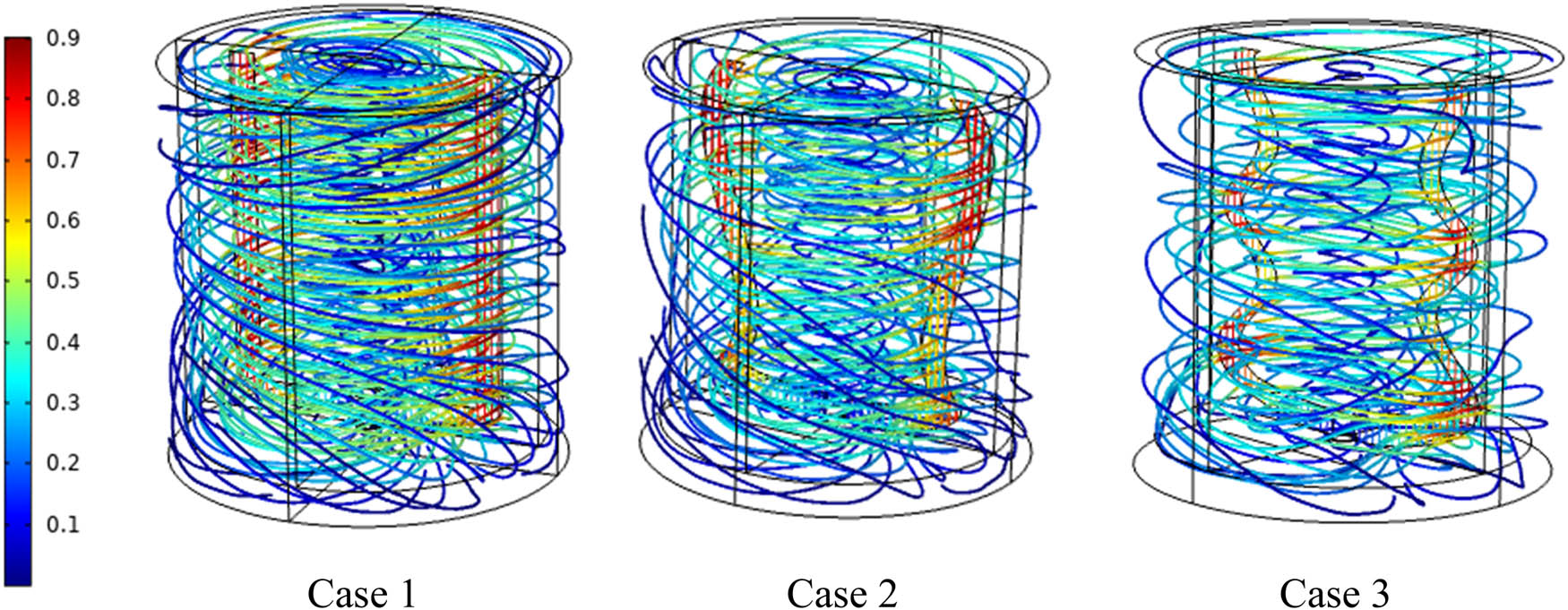
3D streamline outlines in the whole vessel.
Figure 13 shows the power consumption as a function of the Reynolds number at diverse geometrical configurations. It is readily apparent that Case 3 possesses a noteworthy advantage over the other cases due to its remarkably low energy consumption. The disparity in energy usage becomes strikingly evident, as Case 3 consumes a mere fraction of the energy consumed by the alternative cases. In fact, the energy consumption of Case 3 is five times lower when compared to the energy consumption of the other cases. This significant discrepancy in energy efficiency highlights the substantial benefits offered by Case 3, making it a highly favorable choice in terms of minimizing energy requirements and optimizing overall operational costs.
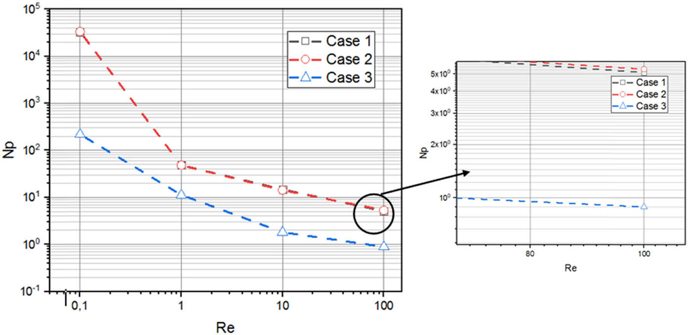
Power consumption as a function of a Reynolds quantity for different geometrical configurations.
6.3 Effect of blade number
In this section, the effect of blade numbers on the hydrodynamic structure (flow pattern, well-moving zone, and power consumption) is represented. In this part of the study, the number of blades increased for the geometrical configurations (Cases 1–3) to obtain new three geometrical configurations (Cases 4–6). Each configuration has four blades.
Based on the findings depicted in Figure 14, it is evident that increasing the number of blades has a notable effect on enlarging the well-moving zone. Among the compared cases, Case 6 emerges as the optimal configuration for enhancing the flow pattern. Notably, Case 6 exhibits the widest sheared zone, extending from the impeller plane to the vessel wall.
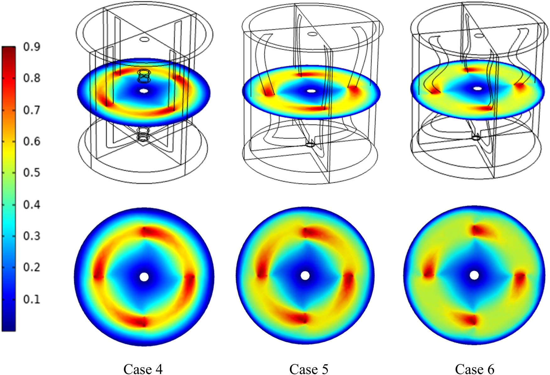
Velocity distribution on the vessel (3D and 2D views) for different geometrical configurations with four blades.
Figure 15 clearly demonstrates the energy consumption across different geometrical configurations, where it becomes evident that the power values remain consistent across the entire range of Reynolds Numbers (
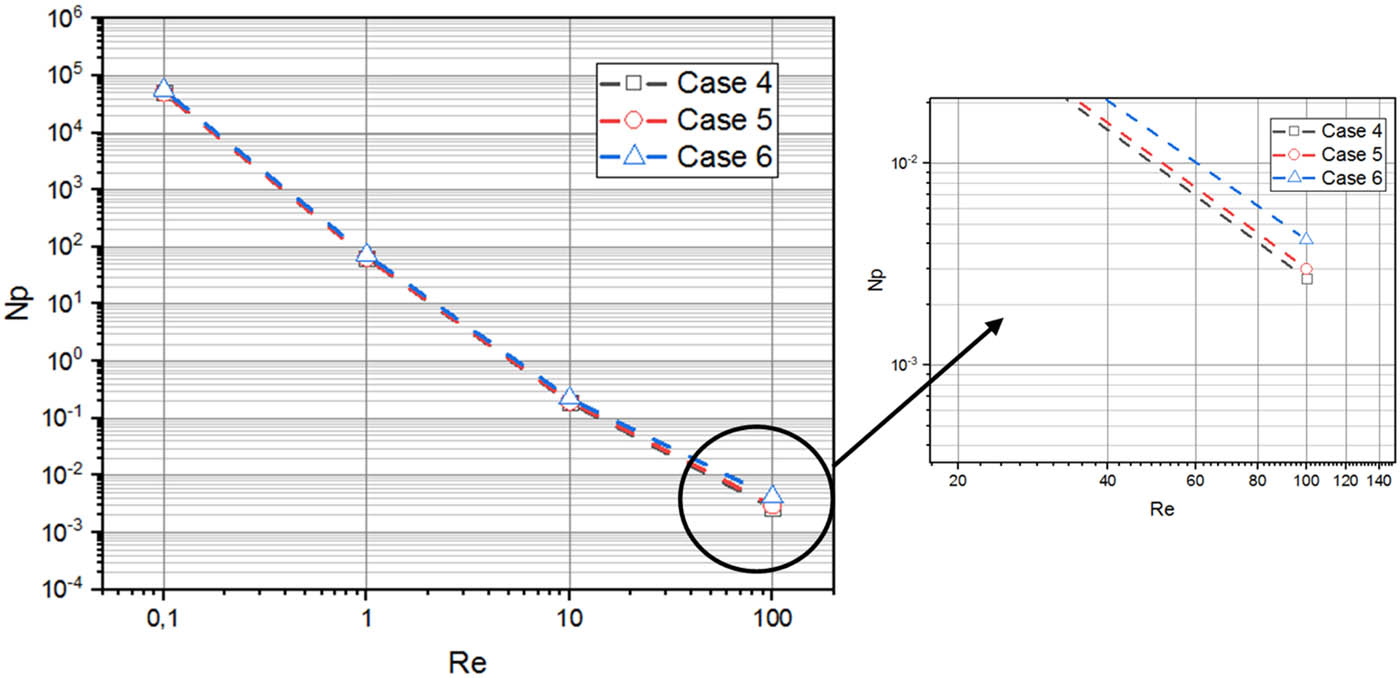
Power consumption as a function of a Reynolds quantity for different geometrical configurations (
6.4 Effect of plasticity
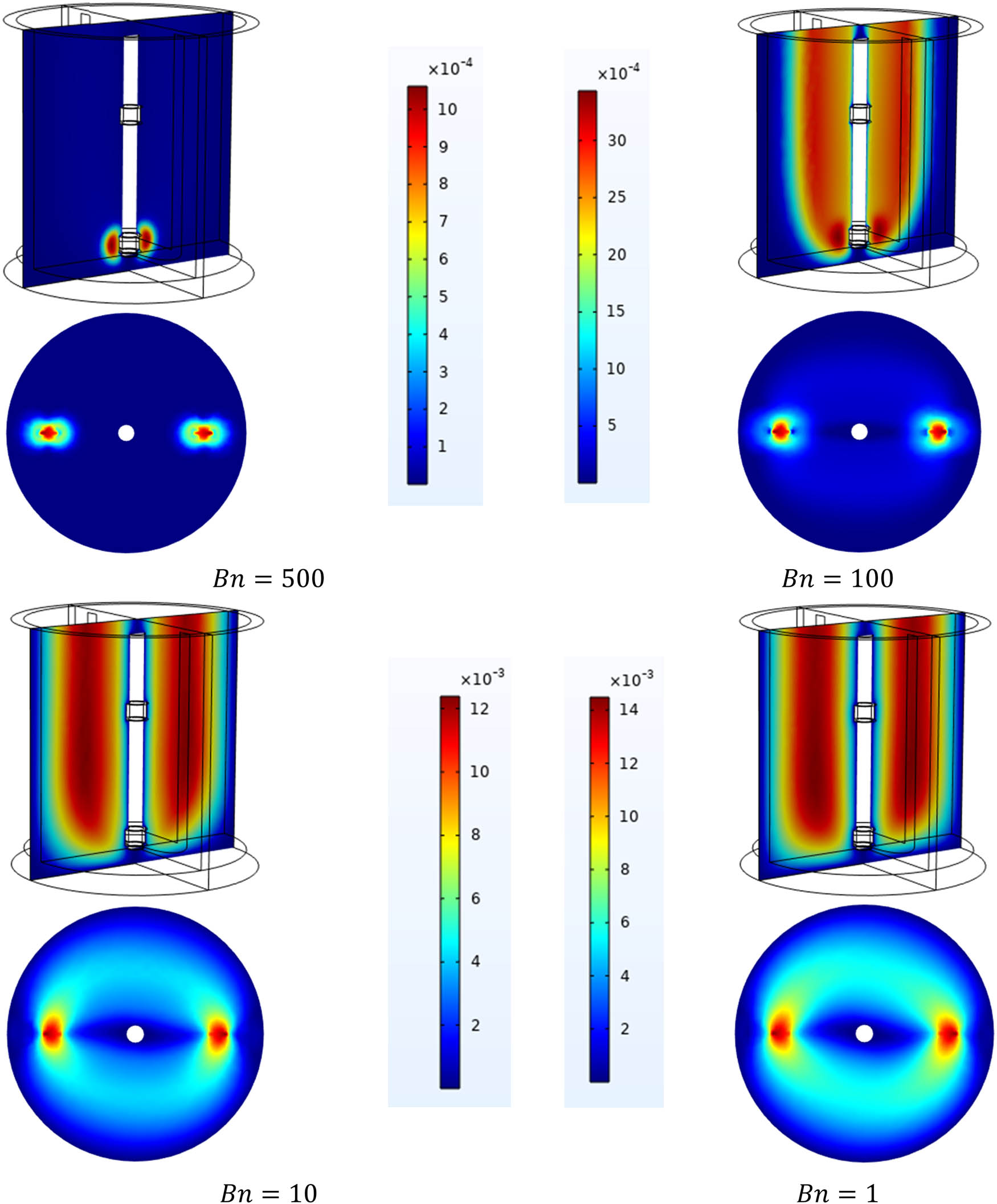
The impression of plastic parameter
From the results shown in Table 3, it was found that for low Bingham numbers (
Power consumption versus plasticity parameter values (
|
|
|
||
|---|---|---|---|
| Case 1 | Case 2 | Case 3 | |
| 1 | 367.5 | 460.19 | 399 |
| 10 | 691.7 | 683.5 | 649 |
| 100 | 2132.6 | 1495.6 | 3,029 |
| 500 | 10,493 | 6731.9 | 11,181 |
Figures 16–18 show velocity distribution along with the stirred tank for Cases 1, 2, and 3, separately. From the consequences, it can be observed from all cases that with a high value of plasticity (
Velocity distribution along with the stirred container (vertical and horizontal sectors) Case 1 with diverse plasticity amounts Bn (1–500).
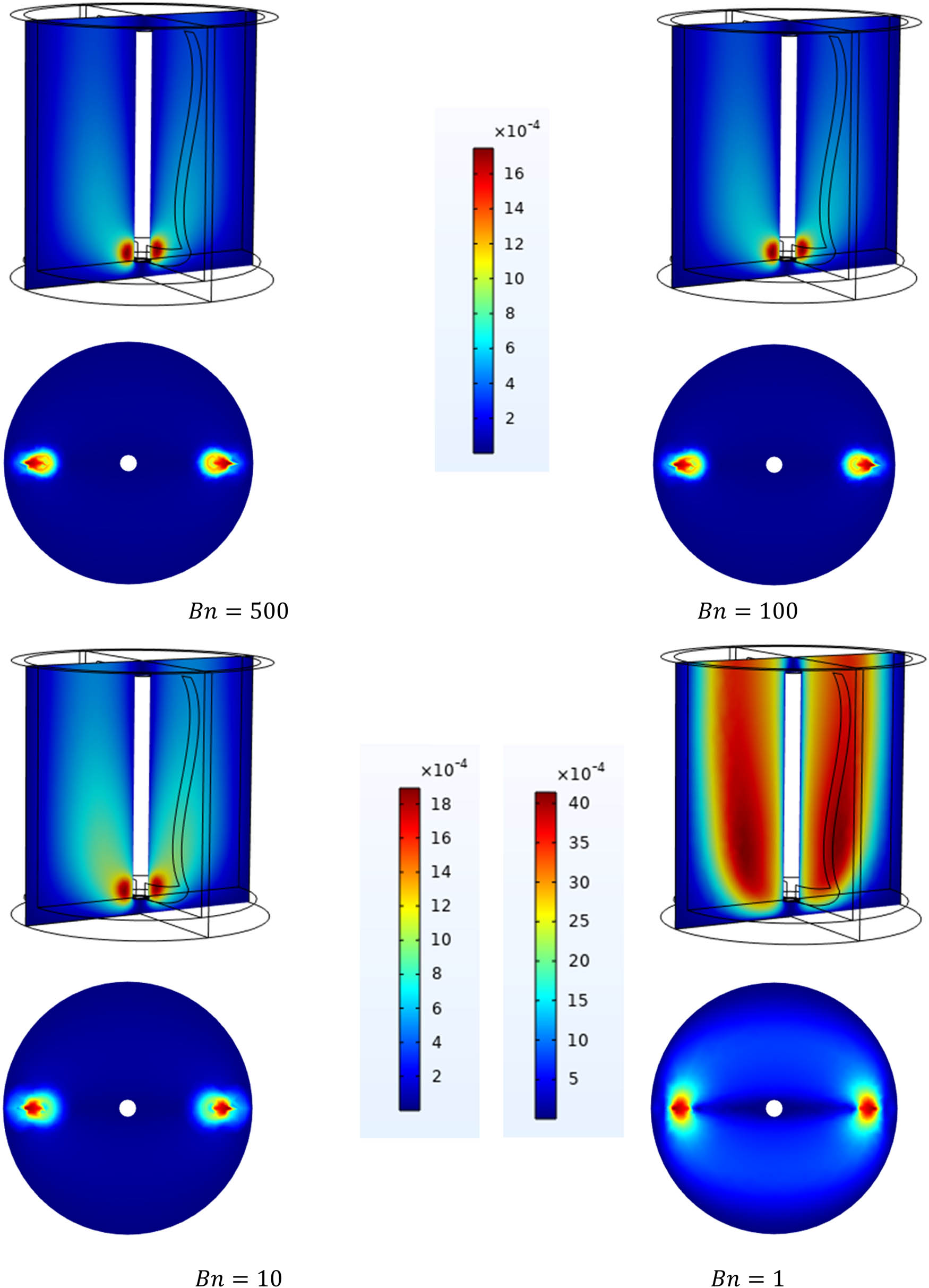
Velocity distribution along with the stirred container (vertical and horizontal sectors) Case 2 with diverse plasticity quantities
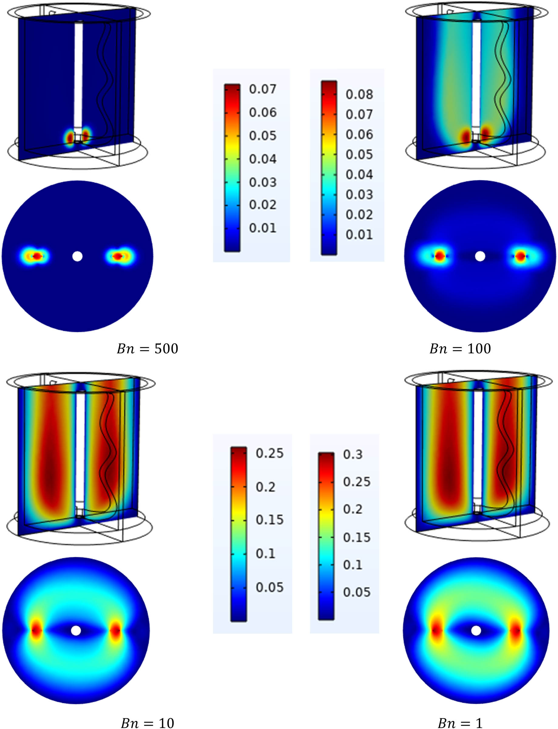
Velocity distribution along with the stirred container (vertical and horizontal sectors) Case 3 with diverse plasticity quantities
7 Conclusion
In this work, the hydrodynamic behavior of viscoplastic liquid within the stirred container has been investigated numerically. The study was undertaken for different inertia values (
The increase in inertia value gives a considerable improvement in the movement zone along with the mixing tank, as was seen in the distribution of streamlines.
At low plasticity parameter values (
For low plasticity parameter values (
The influence of geometrical modification of the anchor impeller shape on the main parameter of mixing flow is obvious in terms of power consumption and flow pattern. Case 3 has been found to be the less energy-consuming case by five times, i.e., Case 1 and Case 2 with
Case 3 is characterized by a big influence on flow circulation and low energy consumption, and therefore, the anchor impeller of Case 3 could be chosen as sufficient for obtaining the best performance.
Acknowledgments
The researchers would like to express their heartfelt appreciation to the Islamic University of Madinah, Saudi Arabia for the support provided to this research work.
-
Funding information: The researchers would like to express their heartfelt appreciation to the Islamic University of Madinah, Saudi Arabia for the support provided to this research work.
-
Author contributions: All authors have accepted responsibility for the entire content of this manuscript and approved its submission.
-
Conflict of interest: The authors state no conflict of interest.
-
Data availability statement: All data generated or analyzed during this study are included in this published article [and its supplementary information files].
References
[1] Ameur, H. Modifications in the Rushton turbine for mixing viscoplastic fluids. Journal of Food Engineering, Vol. 233, 2018, pp. 117–125.10.1016/j.jfoodeng.2018.04.005Search in Google Scholar
[2] Hami, O., B. Draoui, B. Mebarki, L. Rahmani, and M. Bouanini. Numerical model for laminar flow and heat transfer in an agitated vessel by inclined blades anchor. Proceedings of CHT-08 ICHMT International Symposium on Advances in Computational Heat Transfer, Begel House Inc., 2008.10.1615/ICHMT.2008.CHT.1270Search in Google Scholar
[3] Rahmani, L., O. Seghier, B. Draoui, and E. Benachour. Study of blades inclination influence of gate impeller with a non-Newtonian fluid of Bingham. EPJ Web of Conferences, EDP Sciences, 2016, p. 02101.10.1051/epjconf/201611402101Search in Google Scholar
[4] Benhanifia, K., F. Redouane, R. Lakhdar, M. Brahim, K. Al-Farhany, W. Jamshed, et al. Investigation of mixing viscoplastic fluid with a modified anchor impeller inside a cylindrical stirred vessel using Casson–Papanastasiou model. Scientific Reports, Vol. 12, No. 1, 2022, id. 17534.10.1038/s41598-022-22415-6Search in Google Scholar PubMed PubMed Central
[5] Brahim, M., K. Benhanifia, W. Jamshed, K. Al-Farhany, F. Redouane, M. R. Eid, et al. Computational analysis of viscoplastic nanofluid blending by a newly modified anchorage Impeller within a stirred container. Symmetry, Vol. 14, No. 11, 2022, id. 2279.10.3390/sym14112279Search in Google Scholar
[6] Komoda, Y. and T. Date. Enhancement of laminar mixing by an anchor impeller with rotationally reciprocating motion. AIP Advances, Vol. 12, 2022, id. 015013.10.1063/5.0075750Search in Google Scholar
[7] Mebarki, B., B. Draoui, L. Rahmani, M. Bouanini, M. Rebhi, and E. hadj Benachour. Numerical study of mechanical stirring in case of yield stress fluid with circular anchor impeller. Sensors & Transducers, Vol. 132, 2011, id. 108.Search in Google Scholar
[8] Ameur, H. Effect of some parameters on the performance of anchor impellers for stirring shear-thinning fluids in a cylindrical vessel. Journal of Hydrodynamics, Vol. 28, 2016, pp. 669–675.10.1016/S1001-6058(16)60671-6Search in Google Scholar
[9] Kazemzadeh, A., F. Ein-Mozaffari, A. Lohi, and L. Pakzad. Investigation of hydrodynamic performances of coaxial mixers in agitation of yield-pseudoplastic fluids: Single and double central impellers in combination with the anchor. Chemical Engineering Journal, Vol. 294, 2016, pp. 417–430.10.1016/j.cej.2016.03.010Search in Google Scholar
[10] Ameur, H. and A. Ghenaim. Mixing of complex fluids in a cylindrical tank by a modified anchor impeller. Chemistry Select, Vol. 3, 2018, pp. 7472–7477.Search in Google Scholar
[11] Kamla, Y., H. Ameur, A. Karas, and M. I. Arab. Performance of new designed anchor impellers in stirred tanks. Chemical Papers, Vol. 74, 2020, pp. 779–785.10.1007/s11696-019-00902-xSearch in Google Scholar
[12] Kada, B., R. Lakhdar, M. Brahim, and H. Ameur. Agitation of complex fluids in cylindrical vessels by newly designed anchor impellers: Bingham-Papanastasiou fluids as a case study. Periodica Polytechnica, Mechanical Engineering, Vol. 66, 2022, pp. 109–119.10.3311/PPme.18438Search in Google Scholar
[13] Yusof, N. F. M., E. U. E. Soon, I. F. Ismail, and A. N. Mohammed. Mixing performance of anchor and helical stirrer blades for viscous fluid applications. CFD Letters, Vol. 13, 2021, pp. 58–71.10.37934/cfdl.13.1.5871Search in Google Scholar
[14] Driss, Z., A. Salah, D. Driss, B. Necib, H. Kchaou, and M. S. Abid. CFD investigation of the hydrodynamic structure around a modified anchor system. CFD Techniques and Energy Applications, Springer: 2018, pp. 129–150.10.1007/978-3-319-70950-5_6Search in Google Scholar
[15] Wu, H. and G. Patterson. Laser-doppler measurements of turbulent-flow parameters in a stirred mixer. Chemical Engineering Science, Vol. 44, 1989, pp. 2207–2221.10.1016/0009-2509(89)85155-3Search in Google Scholar
[16] Rahmani, L., B. Draoui, M. Bouanini, and E. Benachour. CFD study on heat transfer to Bingham fluid during with gate impeller. Advances and Applications in Fluid Mechanics, Vol. 7, 2013, pp. 1074–1079.Search in Google Scholar
[17] Hammami, M., A. Chebbi, and M. Baccar. Numerical study of hydrodynamic and thermal behaviors of agitated yield-stress fluid. Mechanics & Industry, Vol. 14, 2013, pp. 305–315.10.1051/meca/2013070Search in Google Scholar
[18] Benmoussa, A., L. Rahmani, and M. Rebhi. Regularization model effect on yield stress fluids behavior in a rotating vessel. Advances and Applications in Fluid Mechanics, Vol. 19, No. 3, 2016, pp. 507–515.10.17654/FM019030507Search in Google Scholar
[19] Ameur, H. and Y. Kamla. Geometrical modifications of the anchor impeller to enhance the overall performances in stirred tanks. Instal, Vol. 6, 2020, pp. 42–45.Search in Google Scholar
[20] Kamla, Y., H. Ameur, M. I. Arab, and B. Azeddine. Data on the hydrodynamics and power consumption induced by modified anchor impellers in cylindrical tanks. Data in Brief, Vol. 39, 2021, id. 107669.10.1016/j.dib.2021.107669Search in Google Scholar PubMed PubMed Central
[21] Rahmani, L., B. Draoui, B. Mebarki, M. Bouanini, E. Benachour, and B. Allaoua. Comparison of power consumption for viscoplastic fluid in a rotating vessel with anchor, gate and two blades impellers. International Review of Mechanical Engineering, Vol. 3, 2009, pp. 627–631.Search in Google Scholar
[22] Rahmani, L., B. Draoui, E. Benachour, B. Mebarki, and O. Seghier. A comparative study of two mechanical agitated system in case of non-Newtonian fluids. International Review of Mechanical Engineering, Vol. 7, 2013, pp. 1044–1052.Search in Google Scholar
[23] Ameur, H. and A. Ghenaim. Mixing of complex fluids in a cylindrical tank by a modified anchor impeller. ChemistrySelect, Vol. 3, 2018, pp. 7472–7477.10.1002/slct.201801047Search in Google Scholar
[24] Hadjeb, A., M. Bouzit, Y. Kamla, and H. Ameur. A new geometrical model for mixing of highly viscous fluids by combining two-blade and helical screw agitators. Polish Journal of Chemical Technology, Vol. 19, 2017, pp. 83–91.10.1515/pjct-2017-0053Search in Google Scholar
[25] Jo, H. J., H. K. Jang, Y. J. Kim, and W. R. Hwang. Analyses of dynamical systems structures and mixing patterns in an anchor agitator. Journal of Chemical Engineering of Japan, Vol. 51, 2018, pp. 136–142.10.1252/jcej.17we013Search in Google Scholar
[26] Prajapati, P. and F. Ein‐Mozaffari. CFD investigation of the mixing of yield‐pseudoplastic fluids with anchor impellers. Chemical Engineering & Technology: Industrial Chemistry‐Plant Equipment‐Process Engineering‐Biotechnology, Vol. 32, 2009, pp. 1211–1218.10.1002/ceat.200800511Search in Google Scholar
[27] Papanastasiou, T. C. Flows of materials with yield. Journal of Rheology (Easton, Pennsylvania), Vol. 31, 1987, pp. 385–404.10.1122/1.549926Search in Google Scholar
[28] Marouche, M., D. Anne-Archard, and H. Boisson. A numerical model of yield stress fluid dynamics in a mixing vessel. Applied Rheology, Vol. 12, 2002, pp. 182–191.10.1515/arh-2002-0010Search in Google Scholar
© 2023 the author(s), published by De Gruyter
This work is licensed under the Creative Commons Attribution 4.0 International License.