Download as xlsx, pdf, or txt
You might also like
- Tender For Construction of High Rise Group Housing (Mivan Construction) Technical BidDocument128 pagesTender For Construction of High Rise Group Housing (Mivan Construction) Technical BidSAKULNo ratings yet
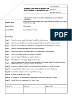
- Installation Checklist For SPV Module: Sterling and Wilson Document No.: SW-SEPC-ICL-PV-002, Rev: 01Document2 pagesInstallation Checklist For SPV Module: Sterling and Wilson Document No.: SW-SEPC-ICL-PV-002, Rev: 01Adithi RNo ratings yet
- Karnataka Electrical Inspectorate) Rules, 2018Document38 pagesKarnataka Electrical Inspectorate) Rules, 2018Babu BabuNo ratings yet
- Megawatt ProposalDocument3 pagesMegawatt Proposalsolomon thambirajNo ratings yet
- Snake Tray Solar BrochureDocument12 pagesSnake Tray Solar Brochurenofal aliNo ratings yet
- 199.8Kw I&C Proposal-1Document5 pages199.8Kw I&C Proposal-1Abuzar BanderkarNo ratings yet
- Shri Vaari Profile.Document54 pagesShri Vaari Profile.anandpurushothamanNo ratings yet
- Warehouse EIADocument110 pagesWarehouse EIAsri kanthNo ratings yet
- DPR Taluk Hospital NeelashwaramDocument17 pagesDPR Taluk Hospital NeelashwaramsunojNo ratings yet
- Modeling Custom Shapes in STAAD PRODocument4 pagesModeling Custom Shapes in STAAD PROKiran KoraddiNo ratings yet
- Miscella Neous Civil Works: SR - Description Unit Rate Quantity AmountDocument7 pagesMiscella Neous Civil Works: SR - Description Unit Rate Quantity AmountSenthilnathan NagarajanNo ratings yet
- Kerala State Electricity Board: Form of Application For Supply of ElectricityDocument43 pagesKerala State Electricity Board: Form of Application For Supply of ElectricityManisha DubeyNo ratings yet
- Purlin Design - Hat-Section@170 (r0)Document4 pagesPurlin Design - Hat-Section@170 (r0)Prince MittalNo ratings yet
- VKBSDocument40 pagesVKBSharish_sekarNo ratings yet
- Completion Certificate GoudagudaDocument2 pagesCompletion Certificate GoudagudasatyabannayakNo ratings yet
- Solar Power Business Scenario in IndiaDocument79 pagesSolar Power Business Scenario in Indiatek_surinderNo ratings yet
- 373 - Offer For C.M.V. Marriage Hall - 45kVA - RKDocument6 pages373 - Offer For C.M.V. Marriage Hall - 45kVA - RKHarish S KiranNo ratings yet
- Scorpius SRT 60 ROW Tracker DatasheetDocument4 pagesScorpius SRT 60 ROW Tracker DatasheetPhani ArvapalliNo ratings yet
- Company Profile ARPSLDocument7 pagesCompany Profile ARPSLSharafat AliNo ratings yet
- Devi Construction PVT - Exp Letter.143Document1 pageDevi Construction PVT - Exp Letter.143Bheemm Bomjan Professional TrainerNo ratings yet
- Plant-Wise Details of RE Installed Capacity-Merged PDFDocument1,958 pagesPlant-Wise Details of RE Installed Capacity-Merged PDFDhruv GoyalNo ratings yet
- List of Approved Vendor As On 22.09.14Document37 pagesList of Approved Vendor As On 22.09.14Pranay PatelNo ratings yet
- Tremix ConcreteDocument37 pagesTremix ConcretethinkwinNo ratings yet
- Report To Ahmedabad OfficeDocument43 pagesReport To Ahmedabad OfficeKuldeep ChakerwartiNo ratings yet
- Po 01-04-2022Document6 pagesPo 01-04-2022Darvesh GuptaNo ratings yet
- Goldi Solar PVT LTD - NoteDocument3 pagesGoldi Solar PVT LTD - NotevaibhavNo ratings yet
- Mumbai International Airport PVT LTDDocument3 pagesMumbai International Airport PVT LTDSraz Midnite100% (1)
- Wo 33771Document9 pagesWo 33771Sabyasachi BangalNo ratings yet
- Havells Wire List Price 19th April 2024Document11 pagesHavells Wire List Price 19th April 2024sanjaymeenadjbNo ratings yet
- SkipperDocument25 pagesSkipperMayank MishraNo ratings yet
- Tamilnadu Coke and Power PVT LTD - 1.3 MWP - Mono - Finance - ProposalDocument35 pagesTamilnadu Coke and Power PVT LTD - 1.3 MWP - Mono - Finance - ProposalsyamprasadNo ratings yet
- Udyog Aadhaar Registration CertificateDocument1 pageUdyog Aadhaar Registration CertificateAkash Bhattiya0% (1)
- Prefabricated House Technical Specification 2021 PDFDocument3 pagesPrefabricated House Technical Specification 2021 PDFPAUL DEREK MALANUMNo ratings yet
- 2 Atta Chakki PlantDocument1 page2 Atta Chakki PlantPrashantSinghNo ratings yet
- ConstructionWeekOnline - SPCLDocument20 pagesConstructionWeekOnline - SPCLAnupa VinnyNo ratings yet
- Supply Erection of 400kv Lines Two CondDocument30 pagesSupply Erection of 400kv Lines Two ConddineshksenthilNo ratings yet
- 33 KV - 11Mtrs Single Pole With V-Cross Arm - ADocument1 page33 KV - 11Mtrs Single Pole With V-Cross Arm - ARashesh PatnaikNo ratings yet
- Africa SolarDocument80 pagesAfrica SolarVincsNo ratings yet
- Amnd 1Document8 pagesAmnd 1rajasekharan kgNo ratings yet
- CPWD Enlistment Rule 2022Document73 pagesCPWD Enlistment Rule 2022Assistant Engineer Elect CED III CCUNo ratings yet
- Parul Institute of Engineering & Technology - Diploma StudiesDocument12 pagesParul Institute of Engineering & Technology - Diploma StudiesJEET SHARMANo ratings yet
- Maitriya Foundation Nepal: Summary of CostDocument62 pagesMaitriya Foundation Nepal: Summary of CostRoshan KejariwalNo ratings yet
- SAP Quotation - ExampleDocument4 pagesSAP Quotation - Examplesusmita jenaNo ratings yet
- Statement of Working Drawings: Calculation Scheme of SCHSDocument71 pagesStatement of Working Drawings: Calculation Scheme of SCHSaayushNo ratings yet
- Hariom Work OrderDocument2 pagesHariom Work OrderAman DubeyNo ratings yet
- KWIPL 12MW WPP Tentative Evacuation KPTCL Approval LetterDocument6 pagesKWIPL 12MW WPP Tentative Evacuation KPTCL Approval LetterAJEESH ASHOKKUMARNo ratings yet
- Power Transmission Companies - IndiaDocument2 pagesPower Transmission Companies - IndiaAkash TyagiNo ratings yet
- Dholera Airport OpeningDocument1 pageDholera Airport OpeningHarshit DubeyNo ratings yet
- Cat. VOG-11 (13.8 KV)Document2 pagesCat. VOG-11 (13.8 KV)djavierNo ratings yet
- Quotation 1Document37 pagesQuotation 1Nikhil SutharNo ratings yet
- A One Engineering Design and Construction Pvt. LTD.: Hatiban Chowk, Lalitpur - 23Document1 pageA One Engineering Design and Construction Pvt. LTD.: Hatiban Chowk, Lalitpur - 23rahul100% (3)
- CV - Md. Rakibur RahmanDocument3 pagesCV - Md. Rakibur RahmanMustafa HussainNo ratings yet
- SOP-14 AGEL-P02-SP02-Module Mounting Structure - Installation of MMSDocument159 pagesSOP-14 AGEL-P02-SP02-Module Mounting Structure - Installation of MMSVikas SinghNo ratings yet
- Specifications For Earthing & Lightning ProtectionDocument3 pagesSpecifications For Earthing & Lightning ProtectionVenu GopalNo ratings yet
- Techno Commercial Proposal 4500kwDocument13 pagesTechno Commercial Proposal 4500kwcapankajabuNo ratings yet
- TRIDENT - Request For ProposalDocument81 pagesTRIDENT - Request For ProposalPrince Mittal0% (1)
- QMS-WI-OMS-09 Replacement of PV ModulesDocument2 pagesQMS-WI-OMS-09 Replacement of PV ModulesRamakantNo ratings yet
- Lab Name: Installation Process of PV Solar System and It's ComponentsDocument12 pagesLab Name: Installation Process of PV Solar System and It's ComponentsFarhan EdwinNo ratings yet
- Back Filling Work Method StatmentDocument2 pagesBack Filling Work Method StatmentAbu NijamNo ratings yet
- Safe Work Method StatementDocument2 pagesSafe Work Method StatementAshby Kb100% (1)
- Special CoDocument3 pagesSpecial CoajNo ratings yet
- LunchDocument1 pageLunchajNo ratings yet
- Urmila Sports Academy, Hansiyawas 16.8 KWP Solar PlantDocument1 pageUrmila Sports Academy, Hansiyawas 16.8 KWP Solar PlantajNo ratings yet
- Material Performance Data Sheet: Corrugated Flexible Tube For Electrical WiringDocument1 pageMaterial Performance Data Sheet: Corrugated Flexible Tube For Electrical WiringajNo ratings yet
- Mms TceDocument7 pagesMms TceajNo ratings yet
- 2 X 6Document7 pages2 X 6ajNo ratings yet
- RPK Al Umi Ni Um Modul e Mount I NG ST R Uc T Ur eDocument4 pagesRPK Al Umi Ni Um Modul e Mount I NG ST R Uc T Ur eajNo ratings yet
- Thanks For Riding, Apoorv: Total 187.63Document2 pagesThanks For Riding, Apoorv: Total 187.63ajNo ratings yet
- Standard Operating Procedure For MMS & Module Re-Installation WorkDocument1 pageStandard Operating Procedure For MMS & Module Re-Installation WorkajNo ratings yet
- Techincal Specification For Geo-TechDocument45 pagesTechincal Specification For Geo-TechajNo ratings yet
- Plan View Isometric View: RPK-SE-942Document1 pagePlan View Isometric View: RPK-SE-942ajNo ratings yet
- Isometric View: Concept Drawing RPK-SE-947Document1 pageIsometric View: Concept Drawing RPK-SE-947ajNo ratings yet
- PARKINGDocument1 pagePARKINGajNo ratings yet
- Mannum Report - WordDocument26 pagesMannum Report - WordajNo ratings yet
- Optimization and Performance of Bifacial Solar Modules: A Global PerspectiveDocument19 pagesOptimization and Performance of Bifacial Solar Modules: A Global PerspectiveajNo ratings yet
- MergeDocument11 pagesMergeajNo ratings yet
- Anchor Bolt Design IS Code LSDDocument56 pagesAnchor Bolt Design IS Code LSDajNo ratings yet
- AustralianDocument7 pagesAustralianajNo ratings yet
- Design of Purlins: Section 1: Properties of SectionDocument3 pagesDesign of Purlins: Section 1: Properties of SectionajNo ratings yet
- Wind Load Calculations As Per Is 875 Part 3Document10 pagesWind Load Calculations As Per Is 875 Part 3ajNo ratings yet
- Concrete Block Weight Calculation: Design SpecificationDocument6 pagesConcrete Block Weight Calculation: Design SpecificationajNo ratings yet