This document describes various defects that can occur in steel billets during the continuous casting process. Section I defines shape defects such as rhomboidity, bulging, concavity, and transverse depression. Section II covers internal defects like diagonal cracking, intercolumnar cracks, and central porosity/pipe. Section III outlines surface defects including bleed outs, reciprocation marks, and scoring. For each defect, the document provides details on causes and recommended actions to check things like mould alignment, secondary cooling, casting speeds, and lubrication.
1.This slide is about causes of breakouts during continuous casting of steel and remedies about the same
2. It will help to reduce breakouts problem during continuous casting of steel up to 80%
SINOM GROUP CO., LTD. is one of the largest manufacturer of copper mould tube in China. Based on customers requirement, we design, manufacture and install the square copper mould tube, round copper mould tube, beam blank, rectangular copper mould tube, diamond type, non-standard type etc.
This document summarizes the process of preparing a tundish for continuous casting of steel. It discusses what a tundish is, the different lining layers including insulation, backup, and working linings. It details the steps to deskull, cool, and apply each lining layer. Key tundish furniture like the submerged entry nozzle and stopper are also described. The final steps of preheating the tundish and attached equipment before use in continuous casting are outlined.
This document discusses the process of continuous casting of steel. It begins with an overview of steel composition and the continuous casting process, which solidifies molten metal directly into final form. Most metals are produced this way, including over 500 million tons of steel annually worldwide. The document then describes the steelmaking processes of basic oxygen furnaces and electric arc furnaces that prepare the molten steel. It focuses on the design, functions, and importance of tundishes in continuous casting, which hold molten steel and facilitate inclusion removal before casting. Key aspects of tundish design like features, insulation, nozzle placement, and refractory lining application are explained.
The document discusses continuous casting of steel and defects that can occur during the continuous casting process. It provides details on:
- Continuous casting involves delivering liquid metal into a water-cooled copper mold where the cast section is formed and then continuously withdrawn for further solidification. More than 50% of current steel production is continuously cast.
- Defects originate from factors like mold oscillation, mold flux, segregation, and phase transformations. Common defects include cracks, blowholes, inclusions, segregation, and pipes.
- Cracks are caused by mechanical and thermal stresses during casting and processing. Blowholes are caused by insufficient deoxidation or humidity. Inclusions arise from physical-chemical effects
Study Of Bleeding Breakout In Thin Slab CasterShubham Thakur
This documentation deals with the all the processes and sub-processes undergoing in the newly installed department in Tata Steel ,i.e., LD3 & TSCR, mainly focussing on "Bleeding Breakout" problem in TSCR shop.
Ladle Metallurgy: Basics, Objectives and ProcessesElakkiya Mani
Worldwide steel production in 2019 reached 1869 million tons, with China as the largest producer at 996 million tons. India was the second largest steel producer at 111 million tons. Ladle metallurgy involves further refining of molten steel in a ladle after tapping from a converter or electric furnace. It allows for homogenization, deoxidation, desulfurization, and other processes. Key ladle metallurgy techniques include ladle furnace treatment, argon stirring, vacuum degassing, and alloy additions to adjust steel chemistry and properties.
This document discusses the process of steel making. It begins by introducing steel and its types, which are classified based on carbon percentage as carbon steel, stainless steel, and alloy steel. It then describes the main steel making methods. The basic oxygen furnace uses carbon-rich pig iron and oxygen to produce low-carbon steel. The electric arc furnace produces specialty steels by heating scrap metal with an electric arc. Secondary steelmaking processes such as argon oxygen decarburization further refine the steel through decarburization, desulphurization, and alloying.
Continuous casting is a steelmaking process where liquid steel is solidified into a semi-finished billet, bloom, or slab. In this process, liquid steel flows from a ladle into a water-cooled copper mold. As the steel exits the mold, it begins to solidify on the surface while the core remains liquid. The semi-solid steel strand is then cooled further through water sprays to fully solidify it into the desired cross-section. The continuous casting process allows for higher productivity and quality than traditional ingot casting.
The document provides information about the steel melting shop (SMS) at Jindal Steel and Power Limited (JSPL) Raigarh plant. The key points are:
1. The SMS has a capacity of 3.2 million tonnes per year and includes 3 electric arc furnaces, a ladle refining furnace, and vacuum degassing units.
2. The melting process involves charging raw materials into the electric arc furnaces and applying electrical energy to melt them. Secondary refining then occurs in the ladle refining furnace and vacuum degassing units.
3. Final products are continuously cast into blooms, billets, rounds and other sections using various casters like the
End splitting during long products rolling billet quality of rolling processJorge Madias
End splitting occurs because the material being rolled has not enough ductility to withstand the stress to which it is submitted. This may happens for different reasons. Coarse cracks in the billet end, like central or diagonal cracks, weakens the end, particularly when the plane where are located coincides in part with the symmetry plane between rolls. Hot ductility of steel depends on the one hand of their intrinsic features, and on the other hand, on the temperature at which they suffer the stress, and its speed.
It is important to roll the steel within the range of higher ductility at a given deformation speed. This is more critical for steels with inherent low ductility as those containing high sulfur.
The role of MnS stringers is also clear; having S controlled at the lower level of the specification is favorable. Nevertheless it is worth to mention that if caster condition is proper and excessive thermal/mechanical stresses do not arise, very high Mn/S ratio is not necessary.
Bar ends loss temperature faster. Another factor is roll cooling, it has to be correctly oriented, not excessive and keeping the position along the processing time.
In other factors experimental and modeling results are apparently controversial. There is coincidence in the fact that more friction between bar and rolls promotes splitting, but not in factors like roll diameter and reduction.
On the basis of pilot rolling results, plane, box-box, square to round and oval to round passes are favorable to avoid splitting, while oval to square promotes splitting.
Injection metallurgy and ladle furnaces are used to refine molten steel. In injection metallurgy, desulfurizing reagents are injected into the ladle through a lance using argon gas as a carrier, which helps remove sulfur. Ladle furnaces are used to reheat, stir, and refine steel in a ladle. They allow for desulfurization, alloy additions, and inclusion removal. Both processes make use of slag and can reduce sulfur levels to 0.0002%, improving steel properties.
This presentation covers all the processes and sub-processes undergoing in the newly installed department in Tata Steel ,i.e., LD3 & TSCR.
This presentation deals with the all the problems faced by this department midway through the process, and mainly focussing on "Bleeding Breakout" problem in TSCR shop.
Also an attempt is made to improve the so-called problem by suggesting certain measures at the end.
This document discusses various types of defects that can occur in hot rolled steel products, including rolled-in scale, slivers, blisters, edge cracks, folds, laminations, and more. For each defect, it provides details on appearance, possible causes related to production issues, and recommendations for process controls to remedy or prevent the defect. Specific examples with photos are also included at the end to illustrate defects observed in real hot rolled products.
The document discusses the process of thermomechanical treatment (TMT) of steel. It defines TMT as a surface quenching process used to produce steel bars with high strength. The key aspects of TMT are surface quenching to form martensite, self-tempering to refine the microstructure, and final cooling. The mechanical properties of TMT bars depend on factors like the martensite volume fraction, cooling rate, and microstructure of the core.
This document discusses the process of continuous casting of steel. It begins with an introduction and overview of the process. It then describes the three main types of continuous casting machines - vertical mould, vertical mould with bending, and curved mould. It provides details on the equipment, materials, process steps, defects, and modern developments of continuous casting. Some advantages are improved yield, quality, productivity and cost efficiency compared to ingot casting. Disadvantages include the need for a large facility and efficient cooling.
The document summarizes key aspects of secondary steelmaking processes. It discusses homogenization through ladle stirring using argon bubbling or electromagnetic stirring. Degassing processes like ladle degassing and circulation degassing are also covered, which are used to remove gases from steel. Other secondary steelmaking stages discussed include heating in the ladle furnace, deoxidation using aluminum, decarburization in vacuum degassing, and desulphurization in the ladle through slag-metal reactions. Injection metallurgy techniques like powder injection and wire feeding are also summarized for adding alloying elements to molten steel.
This document discusses the deoxidation of steel and inclusion control during steelmaking. It explains that oxygen dissolves in steel during production under oxidizing conditions and must be removed through deoxidation. Common deoxidizers like aluminum, silicon, and manganese are added as they have a high affinity for oxygen and form stable oxides. The thermodynamics and kinetics of the deoxidation reaction are described. Proper stirring of the melt is important to allow the deoxidation products to float to the surface and be removed. Calcium injection can also be used to modify inclusions and make them more globular and easier to remove from the steel.
The document discusses key aspects of blast furnace design and operation, including:
1. Blast furnace productivity depends on optimal gas flow and smooth, rapid burden descent which requires an optimized furnace profile and lines.
2. Effluent gas from the furnace contains 20-30% CO by volume and is cleaned through three stages before use to reduce dust from 7-30 g/m3 to 0.01 g/m3.
3. Stoves are used to heat incoming blast with heat from cleaned furnace gas in a cyclic process, maintaining a steady, preheated blast supply to the furnace.
Slivers are irregular flaky pieces of steel clinging to finished steel sheets with non-metallic inclusions or scales underneath. This document discusses the causes and formation of slivers in thin slab continuous casting.
Key causes of slivers include stress generation in oscillation marks, mold taper, casting speed changes, steel composition, and low surface temperature. Slivers containing non-metallic inclusions form from entrapment of mold flux, slag, or alumina precipitates. Alumina slivers specifically form from reoxidation of aluminum in the ladle furnace or mold due to FeO, MnO in slag.
High casting speeds can also cause sliver formation through entrap
The document discusses the structure and properties of metallurgical slags. It states that slags comprise complex compounds of oxides from gangue minerals and sulphides that protect the metal melt. The structure and properties of slags, such as basicity and viscosity, are controlled by their composition. Network forming oxides like SiO2 form stable hexagonal networks, while network breaking oxides like CaO disrupt these networks. The fraction of ionic and covalent bonding in oxides determines their behavior in slags.
Billet defects pinhole and blowhole formation prevention and evolutionJorge Madias
Pin holes as a surface defect, and blow holes as an inner defect, occur in billet / bloom / beam blank casting, particularly for Si-Mn killed steel cast with metering nozzle and oil lubrication. If they are present in abundance or have a large size, they may originate defects in the rolled products. Their characteristics, factors behind their formation, as well as usual processing conditions that promote their occurrence are discussed. Finally, the evolution of these defects during reheating and rolling is analyzed, with industrial examples
Reheating Furnace in Rolling Mill IndustriesVikas Yadav
In steel plants reheating furnaces are used in hot rolling mills to heat the steel stock (Billets, blooms or slabs) to temperatures of around 1200 deg C which is suitable for plastic deformation of steel and hence for rolling in the mill.
This document discusses inclusion control for clean steel production. It defines inclusions as non-metallic compounds that form separate phases in steel. Strict inclusion control is important for producing quality steel products. Inclusions are assessed and controlled by examining their source, shape, composition and distribution. Common inclusions include oxides, sulfides, and carbides. Modification techniques aim to make inclusions less harmful by modifying their shape, composition and dispersion in the steel matrix. Calcium additions are often used to modify alumina and manganese sulfide inclusions. Proper inclusion control is important at all stages of steelmaking and processing to achieve clean steel.
Effect Of CaO, FeO, MgO, SiO2 and Al2O3 Content of Slag on Dephosphorization ...karun19
Phosphorus has atomic number 15 and it can give up all 5 electrons from its outermost shell to become P5+ or accept 3 electrons to become P3- to attain stable configuration.
This means that phosphorus can be removed both under oxidizing as well as reducing conditions.
But removal of phosphorus under reducing conditions is not practical since its removal is highly hazardous.
Thus P removal is practised mostly under oxidizing conditions(i.e. in Basic Oxygen Furnace).
The document discusses refractories used in steel ladle linings. It describes the key functions of steel ladles in transferring molten steel. Different zones in ladle linings require different refractory materials due to varying temperatures and conditions. Magnesia, dolomite, zircon, carbon and spinel refractories are highlighted as important materials used in slag lines, sidewalls, and bottoms of ladles. Magnesia carbon bricks are well-suited for slag zones due to their thermal properties and corrosion resistance. Monolithic castables based on alumina spinel composites are used in ladle bottoms for their strength, thermal shock resistance and corrosion performance.
Rolling is a metal forming process where metal stock is passed through one or more pairs of rolls to reduce the thickness and increase the length. There are two main types:
1) Hot rolling is performed above the metal's recrystallization temperature for lower pressure and improved ductility. It produces coarse grains and no residual stresses.
2) Cold rolling is performed below the recrystallization temperature, requiring higher pressures but improving dimensions, finish and strength through residual stresses and elongated grains.
Rolling mills are classified by the number of rolls used, including two-high, three-high, four-high and cluster/sendzimir mills. Continuous mills use multiple stands to continuously roll sheet metal.
The document discusses various welding defects including lamellar tearing, porosity, underfill, insufficient
penetration, wagon tracks, arc strikes, and incomplete fusion. Lamellar tearing occurs beneath welds in rolled steel
plate and is caused by transverse strain from welding, a weld orientation parallel to inclusions, and poor material
ductility. Porosity is caused by absorbed gases like nitrogen, oxygen, and hydrogen which become trapped during
solidification. Prevention methods for defects include using proper joint design, welding techniques, materials, and
preheating when necessary. Defects require removal and rewelding to repair.
This document discusses various types of blowholes that can occur in castings, including wet sand blowholes, surface blowholes, subsurface slag reaction blowholes, subsurface blowholes, mould or core gas blowholes, entrapped air blowholes, and chaplet blowholes. For each type of blowhole, the document describes possible causes and suggested remedies to prevent or reduce the occurrence of that specific blowhole type in castings. The document is intended to share information on casting defects in order to help those working in the casting industry address and remedy quality issues.
Common defects in castings include misruns caused by insufficient fluidity, pouring at too low a temperature, too slow pouring, or thin cross-sections. Cold shuts occur when two portions of metal fuse together incompletely due to premature freezing. Shrinkage cavities form from solidification shrinkage restricting the last metal to freeze, often near the top of the casting. Microporosity consists of small voids from localized shrinkage in alloy dendrites. Hot tearing occurs when a casting is restrained from contracting in an unyielding mold during solidification.
This document discusses hot tear defects in castings and methods to prevent them. It provides the following key points:
- Hot tears occur during solidification due to resistance to contraction from molds/cores and uneven temperature gradients. Two conditions are needed - resistance to contraction and variable temperature gradients.
- Preventing methods include using strong molds that collapse slowly, designing castings with uniform thickness, adding chills or ribs to promote faster cooling, and controlling steel chemistry to reduce hydrogen and sulfur levels.
- Case studies using computer simulations show locations of hot zones in castings and how positioning chills or changing mold materials reduces temperatures and prevents hot tears.
Sand casting, investment casting, and die casting were discussed as the main casting methods. Key topics included mold filling and solidification, phase change and shrinkage during solidification, heat transfer considerations, and pattern design guidelines. Variations such as continuous casting and 3D printing of tooling were also mentioned. Environmental issues associated with casting operations like energy usage, emissions, and waste disposal were reviewed.
The document provides an overview of various casting methods including sand casting, investment casting, and die casting. It summarizes the key characteristics of each method such as typical metals used, size range, tolerances, surface finish, and process details. It also discusses related topics such as solidification and shrinkage, heat transfer considerations, pattern design guidelines, process variations, and potential environmental impacts.
Sand casting, investment casting, and die casting are the main casting methods discussed. Key topics include the casting process basics for each, phase change and shrinkage during solidification, heat transfer considerations, and pattern design guidelines. Variations and developments like continuous casting and 3D printing of investment tooling are also covered. Environmental impacts of casting such as energy use and emissions are reviewed.
This document summarizes key aspects of three metal casting methods: sand casting, investment casting, and die casting. It covers the basic processes, materials used, tolerances, surface finishes, design considerations, solidification and heat transfer principles, variations and developments in the technologies, and potential environmental issues. The goal is to provide an overview of the fundamentals and tradeoffs of different casting approaches.
Kinematics of Machinery Digital MaterialARUNPRAKASHS7
Sand casting, investment casting, and die casting are the three main casting methods discussed. Sand casting uses a sand mold and can produce parts in most metals with complex geometries but rough surfaces. Investment casting uses a wax mold and yields complex parts in high temperature alloys with smoother finishes. Die casting injects molten metal into steel dies under pressure for aluminum, zinc, and magnesium alloys with smooth surfaces but moderate geometries. Key casting issues covered include phase change and shrinkage during solidification, heat transfer considerations, and pattern design guidelines. Variations like continuous casting and 3D printing of tooling were presented along with environmental impacts.
The document discusses various manufacturing processes and considerations for component design based on the selected process. It describes primary, secondary and tertiary manufacturing processes and provides details on casting, forging and sheet metal processes. Key factors for casting include part complexity, material properties and economics of production quantities. For forging, important considerations include parting lines, draft angles, fillets and corners to enable uniform metal flow. Sheet metal design must account for material thickness and formability limitations.
This document discusses four main forms of corrosion: galvanic, crevice, pitting, and intergranular corrosion. It provides details on the mechanisms, examples, and factors that contribute to each type. Galvanic corrosion occurs when two dissimilar metals are in contact in an electrolyte. Crevice corrosion is localized corrosion in stagnant areas like joints or cracks. Pitting corrosion produces small pits on metal surfaces. Intergranular corrosion preferentially corrodes grain boundaries in metals. The document examines each type through definitions, diagrams, and real-world corrosion incidents.
The document discusses design considerations for castings. It covers topics such as selecting a suitable casting process and material, designing the part for easy casting, locating gates and risers, avoiding defects, and economics. Key points include designing parts with uniform thickness and gradual changes to prevent shrinkage cavities, adding draft angles for removal from molds, and accounting for shrinkage and machining operations in patterns. Common defects like misruns, cold shuts and shrinkage cavities are also outlined. Economics depends on factors like materials, tooling, production rates and costs of melting, heat treating and inspection.
Pitting corrosion is a localized form of corrosion where small areas of a metal surface corrode preferentially, leading to the formation of pits. Metals that form passive films, like aluminum and steel, are most susceptible. Pitting causes failure through penetration with only a small percentage of weight loss. Key conditions for pitting include the presence of halide ions like chlorine in a passive metal, breaks or defects in the passive film, and stagnant conditions. Pitting initiates through the disruption of the passive film, forming an anode site where dissolution occurs balanced by cathode reactions on surrounding areas.
This document discusses various metal casting processes and defects that can occur. It describes permanent and expandable pattern casting processes like sand casting, shell molding, investment casting, and permanent mold casting. Common casting defects are outlined such as misruns, cold shuts, shrinkage cavities, and sand blows. Inspection methods like visual inspection, dimensional measurements, and non-destructive testing are used to detect defects in castings.
This document discusses different types of weld cracking that can occur, including centerline cracking and heat affected zone cracking. Centerline cracking occurs in the center of a weld bead and can be caused by segregation of low melting point constituents, bead shape, or surface profile. Heat affected zone cracking occurs in the base material next to the weld and is caused by the presence of hydrogen, a susceptible material microstructure, and residual stress. Both types of cracking must be prevented by controlling variables like welding parameters, joint design, filler material selection, and cleaning surfaces to remove moisture.
This document discusses different types of weld cracking that can occur, including centerline cracking and heat affected zone cracking. Centerline cracking occurs in the center of a weld bead and can be caused by segregation of low melting point constituents, bead shape, or surface profile. Heat affected zone cracking occurs in the base material next to the weld and is caused by the presence of hydrogen, a susceptible material microstructure, and residual stress. Both types of cracking must be prevented by controlling welding parameters such as joint design, welding process, filler material selection, and eliminating sources of hydrogen.
Lecture 2 Machine Deterioration and Failure 25.10.2023.pptxFuad611081
The document discusses various types of machine deterioration and failure. It describes common types of ferrous and non-ferrous metals used in machines, such as steel, cast iron, stainless steel, copper, bronze, and aluminum alloys. It then explains common forms of deterioration for these metals, including rusting, corrosion, and pitting. The document also discusses several common causes of machinery failure, such as misalignment, unbalance, resonance, bearing issues, looseness, and flow-related problems. Prevention methods are provided for metal deterioration, including plating and surface treatments.
1) The document discusses various defects that can occur during steel ingot solidification such as pipe, columnar structure, blow holes, and segregation.
2) It provides remedies for preventing these defects, such as using a hot top feeder head to avoid pipe formation and soaking ingots to minimize segregation.
3) The document also covers the mechanisms of ingot solidification, describing how killed, rimmed, and semi-killed steels solidify into chill, columnar, and equiaxed zones within the ingot.
The document discusses several ship failures caused by weld defects. It describes Liberty Ship failures in WWII due to stress concentration and susceptible steel. It also examines more recent failures like the Derbyshire in 1980 which was associated with poor structural strength and design. The document analyzes failure cases in detail using photographs, metallurgical testing, and finite element modeling to understand the root causes, which included poor welds, material defects, corrosion, and inadequate inspection. Proper welding, materials selection, inspection, and risk management are identified as important to prevent future ship failures.
A_MukherjeePresn for engineers good fileZiad Salem
This document discusses the evaluation of roll pass design using software. It describes the objectives of roll pass design which is to reduce the cross-sectional area in each pass to gradually form the desired product profile. It then explains the rolling process and factors to consider in roll pass design like taper percentage, groove angles, and fitting. Finally, it shows an example evaluation of 19 passes to reduce a material's cross sectional area and calculates the required power in each pass.
planning maintenance system for engineersZiad Salem
This document provides guidance on the Planned Maintenance System (PMS) used by the Navy to manage shipboard maintenance. It describes the key elements of the 3M system including Maintenance Requirement Cards, Equipment Guide Lists, feedback reports, and responsibilities of personnel involved in maintenance from the Commanding Officer to work center maintenance personnel. Safety precautions and procedures for documenting maintenance, reporting discrepancies, and scheduling preventative maintenance are also outlined.
This document discusses crankshafts, including their function of converting reciprocating motion to rotational motion, materials used such as forged steel, manufacturing processes like hardening, common failure modes from bending and torsional fatigue, and potential material flaws or processing errors that can lead to failures. Key points covered are the crankshaft's role in an engine, how forces like bending and torsion act on it, common failure analysis methods, and factors that contribute to crankshaft damage.
This document describes the design of a double helical gearbox. It includes the design of the pinion, gear, shafts, bearings, housing and selection of lubricating oil. The power input is 300 kW at 2950 rpm to the pinion which drives the gear at 816.5 rpm. The pinion and gear are designed for a life of 108 cycles using involute helical gears made of steel. Dimensions and material specifications are provided for all components along with diagrams of the assembled gearbox. ISO VG 100 oil is recommended for lubrication based on the sliding speed of the gears.
This document discusses fans and their operation. It defines different types of fans including axial fans like propeller, tube-axial, and vane-axial fans. It also defines centrifugal fans and describes their impeller types like backward curved, forward curved, and airfoil. The document discusses factors that determine the suitable fan type like aerodynamic and operational requirements. It also provides equations for calculating fan power requirements and performance at variable speeds. Examples are given showing potential energy savings from improving fan efficiency or using variable speed control instead of a throttle valve.
The document provides maintenance instructions for an induced draft fan used in a kiln. It discusses checking the fan bearings, motor winding temperature, vibration levels, and noise on a regular basis. Specific maintenance tasks are outlined including checking for oil leaks weekly, alarm and trip conditions, wearing parts to examine, notes on wear patterns, and periodically checking the oil levels of non-drive end bearings. The instructions aim to properly maintain the fan to avoid issues like erosion, excessive vibration, and bearing failure.
Gear Fundamentals & _Failure Analysis.pdfZiad Salem
Scott Ouellette from Rexnord Industries presented on gear fundamentals and failure analysis at the Vibration Institute – Piedmont Chapter meeting in Myrtle Beach, SC on May 5th and 6th, 2016. The presentation covered topics including the different styles of gear reducers, best maintenance practices, common failure modes, and technology enhancements that can extend gear and bearing life. Predictive maintenance using data-driven decisions was emphasized as the most effective approach.
Analysis of Bearing and Shaft Failures in Motors.pdfZiad Salem
This document discusses bearing and shaft failures in electric motors. It provides details on bearing stresses, fundamentals, loading principles, lubrication, failure analysis methodology and common failure modes. The key points are:
- Bearing failures account for 50-65% of motor failures, with improper lubrication, contamination, excessive loads and vibration being common causes.
- Proper lubrication and avoiding contamination are critical for bearing life. Grease is most common for small/medium motors, with polyurea greases suitable for higher temperatures.
- A methodology is presented to accurately diagnose bearing failures which considers the failure mode, pattern, appearance, application and maintenance history. The most common failure modes result from fatigue, fret
The document provides an overview of a PLC basics course. It begins with 20 questions about PLC history and applications. It then outlines that the course will familiarize students with PLC structure, operation, and interfaces. It will explain the central processing unit, user memories, and I/O and CPU scans. Students will learn about input/output interfaces, functional operation, and PLC components. The document discusses logic functions, control system options, and why PLCs were adopted. It defines PLCs, describes typical parts and applications. The history of PLC development from the 1960s to distributed control networks is reviewed.
This document discusses rolling bearing failures and their causes. It was produced by Koyo Corporation of USA, a company located in Westlake, Ohio that manufactures and sells bearings. The document examines why bearings may fail and the root causes.
The document discusses the rolling process for metal forming. Rolling is defined as passing metal between rolls to plastically deform it. There are two main types: hot rolling, which is used for initial breakdown of ingots, and cold rolling, which provides closer dimensional tolerances and better surface finishes. Rolling can produce products like plate, sheet, strip, bars, and pipes. The rolling process involves passing metal through sets of rolls under high compressive forces.
This document provides descriptions of various types of cranes, including:
- Mounted cranes like truck cranes and rough terrain cranes that are mobile.
- Specialized cranes like sidelift cranes for containers and all terrain cranes.
- Crawler cranes that move on tracks and tower cranes fixed to buildings for construction.
- Other cranes suited to specific environments like floating cranes, railroad cranes, and aerial cranes.
This PPT covers the index and engineering properties of soil. It includes details on index properties, along with their methods of determination. Various important terms related to soil behavior are explained in detail. The presentation also outlines the experimental procedures for determining soil properties such as water content, specific gravity, plastic limit, and liquid limit, along with the necessary calculations and graph plotting. Additionally, it provides insights to understand the importance of these properties in geotechnical engineering applications.
Algorithm design techniques include:
Brute Force
Greedy Algorithms
Divide-and-Conquer
Dynamic Programming
Reduction / Transform-and-Conquer
Backtracking and Branch-and-Bound
Randomization
Approximation
Recursive Approach
What is an algorithm?
An Algorithm is a procedure to solve a particular problem in a finite number of steps for a finite-sized input.
The algorithms can be classified in various ways. They are:
Implementation Method
Design Method
Design Approaches
Other Classifications
In this article, the different algorithms in each classification method are discussed.
The classification of algorithms is important for several reasons:
Organization: Algorithms can be very complex and by classifying them, it becomes easier to organize, understand, and compare different algorithms.
Problem Solving: Different problems require different algorithms, and by having a classification, it can help identify the best algorithm for a particular problem.
Performance Comparison: By classifying algorithms, it is possible to compare their performance in terms of time and space complexity, making it easier to choose the best algorithm for a particular use case.
Reusability: By classifying algorithms, it becomes easier to re-use existing algorithms for similar problems, thereby reducing development time and improving efficiency.
Research: Classifying algorithms is essential for research and development in computer science, as it helps to identify new algorithms and improve existing ones.
Overall, the classification of algorithms plays a crucial role in computer science and helps to improve the efficiency and effectiveness of solving problems.
Classification by Implementation Method: There are primarily three main categories into which an algorithm can be named in this type of classification. They are:
Recursion or Iteration: A recursive algorithm is an algorithm which calls itself again and again until a base condition is achieved whereas iterative algorithms use loops and/or data structures like stacks, queues to solve any problem. Every recursive solution can be implemented as an iterative solution and vice versa.
Example: The Tower of Hanoi is implemented in a recursive fashion while Stock Span problem is implemented iteratively.
Exact or Approximate: Algorithms that are capable of finding an optimal solution for any problem are known as the exact algorithm. For all those problems, where it is not possible to find the most optimized solution, an approximation algorithm is used. Approximate algorithms are the type of algorithms that find the result as an average outcome of sub outcomes to a problem.
Example: For NP-Hard Problems, approximation algorithms are used. Sorting algorithms are the exact algorithms.
Serial or Parallel or Distributed Algorithms: In serial algorithms, one instruction is executed at a time while parallel algorithms are those in which we divide the problem into subproblems and execute them on different processors.
Kalite Politikamız
Taykon Çelik için kalite, hayallerinizi bizlerle paylaştığınız an başlar. Proje çiziminden detayların çözümüne, detayların çözümünden üretime, üretimden montaja, montajdan teslime hayallerinizin gerçekleştiğini gördüğünüz ana kadar geçen tüm aşamaları, çalışanları, tüm teknik donanım ve çevreyi içine alır KALİTE.
The Uni-Bell PVC Pipe Association (PVCPA) has published the first North American industry-wide environmental product declaration (EPD) for water and sewer piping, and it has been verified by NSF Sustainability, a division of global public health organization NSF International.
Flex and rigid-flex printed circuit boards (PCBs) can be considered at the basic level some of the most complex PCBs in the industry. With that in mind, it’s incredibly easy to make a mistake, to leave something out, or to create a design that was doomed from the start.
Such design failures can end up leading to an eventual failure by delamination, short circuits, damage to the flex portions, and many other things. The easiest way to circumvent these is to start at the beginning, to design with preventing failure in mind rather than trying to fix existing designs to accommodate for problems.
In this webinar, we cover how to design flex and rigid-flex PCBs with failure prevention in mind to save time, money, and headaches, and what failure can look like.
For more information on our flex and rigid-flex PCB solutions, visit https://www.epectec.com/flex.
Biases, our brain and software developmentMatias Iacono
Quick presentation about cognitive biases, classic psychological researches and quite new papers that displays how those biases might be impacting software developers.
1. I.
1.1
1.2
1.3
1.4
1.5
1.6
II.
2.1
2.2
2.3
2.4
III
3.1
3.2
3.3
3.4
3.5
3.6
3.7
3.8
3.9
3.10
3.11
3.12
3.13
3.14
AL-TUWAIRQI STEEL PRODUCTS COMPANY
Quality Control/Quality Assurance Department
BILLET DEFECTS
Slag (Entrapped Scum)
Longitudinal Corner Depression
Transverse Corner Cracks
INTERNAL DEFECTS
Diagonal Cracking
Intercolumnar (Feathers halfway) Cracks
Central Pipe, Central Porosity
Scored Mould (ridges on billet)
Mould Meniscus Chrome Missing
Teeming Arrest
Longitudinal Corner Cracks
Skin Drag
Aluminum Entrapment
Surface Pinholes
Subsurface Blowholes
SURFACE DEFECTS
Reciprocation/Oscillation Marks
Scoring
Hot Shortness
Bleed
SHAPE DEFECTS
Rhomboidity
Bulging
Concavity
Transverse Depression (Low Carbon Steel Type)
Twist
Worn Withdrawal/Straightener Roll Marking
2. I.
1.1
(a.)
(b.)
(i)
(ii)
(iii)
D 1
D 2
Rhomboidity is the distortion from square of the billet to give differing diagonal lengths
SHAPE DEFECTS
Rhomboidity
General
Causes
Uneven mould cooling due to lack of mould taper (Flared mould or negative taper)
Uneven secondary cooling due to either misaligned or blocked sprays
═ %Rhomboidity
Action
Check mould taper
Check Secondary Cooling alignment
Check MS section of mould.
Measurement of Rhomboidity
ΔD ═
D 1- D 2
D 2
x 100
Where: is the larger diagonal length
is the smaller diagonal length
3. 1
(a.)
(b.)
(i)
(ii)
(iii)
Check secondary Cooling alignment and for blocked spray nozzles
Bulging is the distortion of one or more surfaces to produce a surface which is convex, rather
than flat.
Is due to lack of support of a thin shell against the effect of ferrostatic pressure.
This may be cause by:
Casting with excessive superheat and or fast, resulting in thinner than usual shell.
Blocked secondary cooling nozzles resulting in thinner than usual shell.
Action
Bulging
General
Causes
Check casting speed, temperature, mould water flow.
Check MS section of mould.
4. 1.3
spray nozzles.
(i)
Almost invariably has been found to be due to incorrect alignment of secondary cooling or blocked
Action
Check secondary Cooling alignment and for blocked or missing spray nozzles
Concavity
General
Concavity is the distortion of one or more faces (generally one) to produce concave rather than
flat surfaces.
Causes
Concavity and bulging may be associated on the same sample.
5. 1.4
(ref.diagram).
i.e
(i)
Transverse Depressions
General
Check and control casting speeds to SOP range.
Localized depressions across the face of the billet, often being present on all four faces in a
'zone of defect' around the billet.
Causes
Casting too fast for combination of steel type / mould taper.
Billet shrinkage insufficent for mould taper resulting in excessive drag. In extreme instances the billet
can be seem to jump upwards in the 'loop' area (pre-withdrawal drives). This results in the billet
actually 'necking' as in tensile testing with the resulting development of cracks. If the sticking is
severe enough, it will result in breakouts.
The types of steel most prone to this are the very low carbon grades.
ex. 701, 702 (1005 type steels)
Action
6. 1.5
(i) Check for missing / blocked nozzles in the spray apron.
(ii) Check for leaking hoses, pipes or misdirected spray cooling jest in the withdrawal
drive / strainer unit area .
Action
This defect is normally associated with uneven cooling in the spray zone and particularly in the withdrawal
drive/straightener unit area.
General
Twist is when the billet appears to have been twisted around its longitudinal centreline axis.
Causes
Twist
7. 1.6
(i)
Check for alignment and indications on the billet surface.
Worn withdrawal/Straightener Roll Marking
General
These are markings that appear longitudinally all thorughout the billet length most of the times
in regular frequency and pattern.
Causes
This defect is normall associated with worn-out/damaged or unaligned roller surfaces usually on the
straightener area.
Action
Check and change rollers periodically or monitor useful life of roller unit.
(ii)
8. II.
2.1
(a.)
(i)
(ii)
This is generally found associated with rhomboidity, in particular rhomboidity caused by
secondary cooling where there has been twisting of a reasonably thick shell.
Rhomboidity associated with mould defect (lack of taper) does not tend to exhibit this defect to
the same extent.
Often results in a breakout htrough the crack.
Uneven secondary cooling of the billet which gives rise to stress which results in cracks
opening on the corner planes of weakness.
Causes
Check secondary cooling alignment
If secondary cooling appears satisfactopry, check for lack of mould taper
INTERNAL DEFECTS
Diagonal Cracking
General
Action
9. 2.2
(a)
(b)
(i)
(ii)
General
Causes
These form approximately 1/3 to 2/3 of the way between the outside faces and the centre. They
are generally 'hairline' and cannot be seen without macroetching. The location of the cracks
(closer to the outside or centre) is indicative of the relative location of the problem (high or low)
in the cooling zone.
Check casting practice against S.O.P.
Due to thermal stress, the result of uneven secondary cooling
Due to reheating of the billet after excessive cooling (i.e low speed, high water flow).
Action
Check secondary cooling alignmnet and for blocked or missing spray nozzles.
INTERCOLUMNAR FEATHER/HALFWAY CRACKS
10. 2.3
Check casting practice again, against S.O.P., though the 'defect' does not tend to produce rod defecrts in
itself, it may well indicate other potential problems such as segregation on high carbon grades.
CENTRAL PIPE, CENTRAL POROSITY
General
Causes
Central pipe being when there is a defiite single hole in the center of the billet, the hole being of
intermittent nature and extending logitudinally down the billet.
Central porosity is when the center of the billet exhibits a general unsoundness (can sometime
only be seen after macroetching).
(a)
The smaller the section size, the easier it is for the inward growing shell to bridge across the molten
core from surface irregularities and hence create isolated pockets of molten metal which on
solidification leave voids. (solidification shrinkage of steel is approx 7%).
If the temperature (superheat) is high then the molten core is long and narrow and eaasier to bridge
across.
Associated with a number of casting factors such as section size, casting speed and temperature.
Action
The casting speed effect is that if casting fast, the molten core is long and narrow and easier to
bridge across.
(b)
(c)
11. 2.4
(a)
Action
Often the holes can be seen on the billet ends during casting. Providing it is compatible with
specification chemistry, increase the aluminum wire feed rate to the strand.
( i )
If the problem is due to a wire feeder being out of service, plug-off the strand.
SUBSURFACE BLOWHOLES
General
These voids are intercolumnar grain, elongated 5-20mm length in the direction of grain growth.
If they reach the surface or are sufficiently close to the surface that upon reheating of the billet
they will be exposed to air and react to form oxide scale, then they will cause a rod defect.
( ii )
Often the steel may be seen to be rimming slightly in the mould. If this is the case, check the
aluminum feed rate and increase if necessary.
General case
The result of insufficient deoxidation of the steel, the excess oxygen being evolved on solidification (
i.e. the steeel rimming.)
C + O ⇄ CO
Formation of an oxide layer prevents these holes welduing up during rolling.
Cause
12. (b)
Hydrogen arises from two sources, the use of organic binders in cold tundish lining tiles and from the
natural gas use as the shrouding gas on the tuyeres of the converters. It does not normally cause
blowholes by itself but in conjunction with [O] and [N], the higher [H] at start of cast (on a new
tundish) from tile pick up can result in from end blowholes on the first billets from each strand.
Special case
In addition to [O], [N] and [H] can alos casue rimming in the mould and subsequent subsurface
blowholes.
( ii )
The solubility of [N] in pure Fe is 0.043 by weight i.e. 430 ppm. This can result in substantial nitrogen
gain on low carbon steels depending upon steelmaking and LTS practices. In practice for [N], values
of greater than approximately 140ppm [N], are sufficient to cause blowholes. The actual level at
which subsurface blowholes due to [N] will occur will also be dependent upon the residual [O] values
which are dependent upon the Mn and Si levels.
Cause
13. III
3.1
(a.)
(i)
(d.)
May be due to lack of mould taper resulting in a thin shell exiting the mould. Lack of billet/mould
contact will result in a thinner shell due to reduced heat transfer.
If persistent bleeds/breakouts are associated with a particular mould over two consecutive
heats, change the mould.
(ii)
Action
Check secondary cooling for blocked nozzles.
(c.)
Often associated with "dirty" steel (stream condition/stell chemicstry) where a slag inclusion has
fallen out.
SURFACE DEFECTS
BLEED
General
A bleed occurs when molten steel core penetrate through the steel skin. This can occur either
while within the mould or below the mould. If the leak is chilled off by either the mould or the
secondary cooling sprays it is termed a bleed. If casting of the strand has to terminate due to
loss of the molten core from the mould, then it is termed a breakout.
Excessive superheat results in thinner shell hence greater risk.
Excessive casting speed, due to oxygen lancing of a nozzle open and burning out of the bore, will
give thinner shell.
(b.)
Causes
14. 3.2
(a)
(b)
( i ) _
_
_
oil slits not blocked
supply lines have no holes
pumps working
Generally the problem is related to blocked oil slits.
Check mould lubrication
RECIPROCATION/OSCILLATION MARKS
General
These are transverse, parallel marks, the distance between the marks being related to the
amount that the billet has been withdrawn during one oscillation cycle.
Some degree of marking is unavoidable but excessive ridging can cause lapping defects on
rolling.
Action
Causes (of heavy marking)
Incorrect oscillation stroke/cycle rate, for the casting speed.
Lack of mould lubrication.
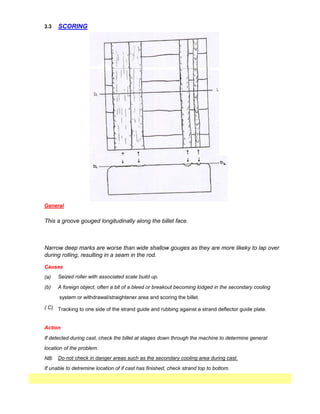
15. 3.3
Causes
(a)
(b) A foreign object, often a bit of a bleed or breakout becoming lodged in the secondary cooling
system or withdrawal/straightener area and scoring the billet.
( C) Tracking to one side of the strand guide and rubbing against a strand deflector guide plate.
If detected during cast, check the billet at stages down through the machine to determine general
location of the problem.
NB:
General
This a groove gouged longitudinally along the billet face.
Narrow deep marks are worse than wide shallow gouges as they are more likeky to lap over
during rolling, resulting in a seam in the rod.
If unable to detremine location of if cast has finished, check strand top to bottom.
Do not check in danger areas such as the secondary cooling area during cast.
Action
SCORING
Seized roller with associated scale build up.
16. 3.4 HOT SHORTNESS
General
This is found when the billet is deformed under tensile conditions at elevated temperatures (i.e.
hot shearing). It is not evident if the billet has been gas cut to length.
The defect shows as a maze of fine transverse cracks on the tensile face of the shear cut.
Causes
The defect is caused by grain boundary precipitation of copper, the problem being accentuated by a 'high'
tin level. This copper, copper/tin precipitate has a low melting point and hence low hot tensile strength.
Action
Check scrap source for copper or brass. If high levels of both tin and copper are present, often from
soldered products scuch as vehicles radiators.
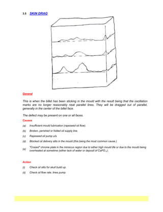
17. 3.5
The defect may be present on one or all faces.
(a)
(b)
(c)
(d)
(i)
(ii)
(e)
Check oil slits for skull build up.
SKIN DRAG
General
Causes
Insufficient mould lubrication (rapeseed oil flow).
Action
This is when the billet has been sticking in the mould with the result being that the oscillation
marks are no longer reasonably neat parallel lines. They will be dragged out of parallel,
generally in the center of the billet face.
Broken, perished or folded oil supply line.
Rapeseed oil pump u/s.
Blocked oil delivery slits in the mould.(this being the most common cause.)
"Crazed" chrome plate in the miniscus region due to either high mould life or due to the mould being
overheated at sometime (either lack of water or deposit of CaPO 4 ).
Check oil flow rate, lines pump.
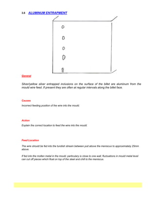
18. 3.6
Silver/yellow silver entrapped inclusions on the surface of the billet are aluminum from the
mould wire feed. If present they are often at regular intervals along the billet face.
Causes
ALUMINUM ENTRAPMENT
The wire should be fed into the tundish stream between just above the meniscus to approximately 25mm
above.
If fed into the molten metal in the mould, particulary is close to one wall, fluctuations in mould metal level
can cut off pieces which float on top of the steel and chill to the meniscus.
Action
Explain the correct location to feed the wire into the mould.
Feed Location
Incorrect feeding position of the wire into the mould.
General
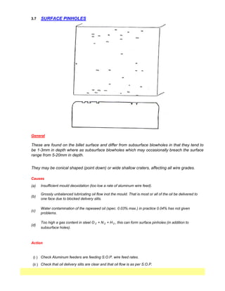
19. 3.7
(a)
(i )
(ii ) Check that oil delivery slits are clear and that oil flow is as per S.O.P.
SURFACE PINHOLES
General
These are found on the billet surface and differ from subsurface blowholes in that they tend to
be 1-3mm in depth where as subsurface blowholes which may occasionally breach the surface
range from 5-20mm in depth.
Causes
Water contamination of the rapeseed oil (spec. 0.03% max.) in practice 0.04% has not given
problems.
Action
(c)
Too high a gas content in steel O 2 + N 2 + H 2 , this can form surface pinholes (in addition to
subsurface holes).
(d)
Check Aluminum feeders are feeding S.O.P. wire feed rates.
They may be conical shaped (point down) or wide shallow craters, affecting all wire grades.
Insufficient mould deoxidation (too low a rate of aluminum wire feed).
Grossly unbalanced lubricating oil flow inot the mould. That is most or all of the oil be delivered to
one face due to blocked delivery slits.
(b)
20. 3.8
NB:
Action
Due to the solidification of the molten core, the defect will extend fro approximately
1000mm down strand from the actual seam on the outside of the billet.
Any billet with a teeming arrest must be either cut back to a short or scrapped.
TEEMING ARREST
General
A teeming arrest occurs when there is a temporary stoppage in the casting of a billet. That is,
the steel is deliverted away from the mould for a short period (laundering).
This results in the solidification of the molten core that was present. Upon restarting, the
moplten steel welds imperfectly to the solid steel present creating conical zone of weakness.
This may tear apart during hot rolling or will create a zone of weakness in the rolled produce.
21. 3.9
(a)
(b)
(i)
(ii)
Check mould.
Check secondary cooling.
This is a depressed groove on the surface of the billet, adjacent to the corner, extending down
the length of the billet.
The defect is often associated with rhombhoidity and longitudinal corner cracks.
Flared mould.
Action
Uneven secondary cooling.
LONGITUDINAL CORNER DEPRESSION
General
Cause
22. 3.10
(a)
(b)
(c)
LONGITUDINAL CORNER CRACKS
Some steels have on past experience proved more prone to cracking, those of approximately
0.05%C and 0.20 wt %C.
Causes
General
Check mould taper and secondary cooling equipment.
Lack of mould taper.
Distortion of mould meniscus area.
Action
Secondary cooling alignment.
These are cracks that occur on the round corner radius of the billet and extend down the length
of the billet. The crack may be continuous or intermittent.
23. 3.11
(a)
(i)
(ii)
(iii)
Action
(b)
If deep and long, are often due to misalignment of the secondary cooling give cold
corners which cracks under the tensile stress of bending straightening.
(c)
Casting slow and cold due to a tundish nozzle problem can also result in cracks because
of steel temperature at bending/straightening.
Check casting speed/temperature of affected stand.
TRANSVERSE CORNER CRACKS
General
These occur on the corner of the billet. They may or may not extend across the full face of the
billet towards the near corners.
They often occur on reciprocation marks (these being places of slight weakness due to welding
folding of the shell during the oscillation cycling).
Check secondary cooling alignment.
Causes
If very shallow, caused by sticking of the billet in the mould.
Check mould lubrication, especially for blocked oil delivery slits.
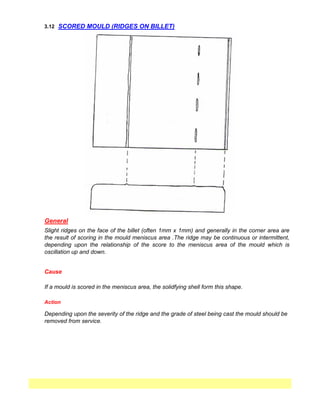
24. 3.12
Action
Depending upon the severity of the ridge and the grade of steel being cast the mould should be
removed from service.
SCORED MOULD (RIDGES ON BILLET)
General
Cause
Slight ridges on the face of the billet (often 1mm x 1mm) and generally in the corner area are
the result of scoring in the mould meniscus area .The ridge may be continuous or intermittent,
depending upon the relationship of the score to the meniscus area of the mould which is
oscillation up and down.
If a mould is scored in the meniscus area, the solidfying shell form this shape.
25. 3.13
A deposit on the outside of the mould will inhibit the heat transfer allowing the mould to heat up
in the insulated area. Because of the large differences in the expansion rates of copper and
chrome, the chrome tends to spall off.
MOULD MENISCUS CHROME MISSING
General
This results in a characteristic form of bleed which is due to tearing of the thin shell in the
meniscus area. In general, the defect is samall, the shell tearing only over the defect, rather
than across the full faces of the meniscus.
Cause
Chrome missing from a spot in the mould meniscus area.
In general, the defect appears almost continuous, occurring on virtually every oscillation band
(dependent upon how steady the casting level is maintained).
Action
Remove mould from service. Check as soon as possible for calcium or phosphate deposit on
the outside of the meniscus area. If present, all moulds should be removed as soon as practical
for cleaning to remove the build up.
26. 3.14
(b)
Action
Causes
Origin is from either deoxidation or reoxidation products.
Deoxidation - carried over from ladle due to chemistry/physical nature of material
Reoxidation - from eihtr reoxidation of alloying in elements in the tundish or mould due to
contact with air (landle and tundish streams)
If not removed from mould (fished out) while floating on the surface, it may/will become
entrapped on the solidyfying meniscus and travel down the mould, creating a depression in the
steel which solidifies around the slag.
(c)
If the problem is due to a poor stream condition on a single strand, then plug-off the strand if
casting conditions (temperature) permit.
(a)
Poor tundish nozzle stream condition will greatly increase the amount of slag generated
and hence the likelihood of a slag problem.
Insufficient fishing/skimming by operator.
Some grades are inherently more susceptible, particularly those with low Mn:Si ratios.
(i.e,. 2.5:1).
General
SLAG (ENTRAPPED SCUM)