DOI: 10.1051/ matecconf/2016 610 6010
MATEC Web of Conferences 61, 06010 (2016)
APOP2016
A Fibre Bragg Grating Interrogation Technique Based on High
Birefringence Fibre Loop Mirror and WDM
Xun Zhang1 Shuyang Hu1,a and Chuan He1
1
School of applied Sciences, Beijing University of Technology, Beijing, 100124, China
Abstract. In this paper, a fibre Bragg grating (FBG) interrogation technique based on high Birefringence
fibre loop mirror (Hi-Bi FLM) and wavelength division multiplexer (WDM) is proposed and demonstrated.
The approximate linear edge of the transmittance of the Hi-Bi FLM, which is a sinusoidal function of
wavelength, is used to interrogate the sensing FBGs and WDMs is used to realize wavelength
discrimination .Suitable for both static and dynamic sensing, this interrogation method has the advantages of
all fibre design and high stability.
1 Introduction
Fibre Bragg grating has been applied broader and broader
because of its many advantages. The critical aspect
related to the practical use of an FBG sensor is the
necessity of performing accurate measurement of the
small wavelength shift associated with thermal and strain
state changes. To facilitate the broad use of this class of
sensors, compact, rugged, wide range and low cost
interrogation systems are required. In addition,
improvements in the fabrication of FBGs using phase
mask techniques have reduced the cost of grating
fabrication so that the interrogation unit, rather than the
sensorˈaccounts for a large proportion of the cost of a
complete sensing system .Among the often used technic
such as Matched-filter interrogation technique [1] ,
interferometric Fourier transform technique [2] and the
technic using tunable light source[3], the edge filter
demodulation technic in which the FBG is interrogated
by measuring the power of the output light has the
advantages such as high demodulation speed, cheapness,
convenience and both suitable for both static and
dynamic measurement. On the other hand the optical
fiber-loop mirror has been used in several applications,
namely in optical communications like a terahertz optical
asymmetric demultiplexer [4] or a nonlinear optical loop
mirror [5]. In the optical sensor, it has been used as a
Sagnac interferometer for temperature measurement [6].
High birefringence fiber loop mirror (Hi-Bi FLM) has
been used as edge filter to interrogate the FBG sensors in
recent years [7,8]. In 2001, Seunghwan Chung reported a
FBG demodulating technic [9] using Hi-Bi FLM with the
resolution of 2.12ȝİ. Zhouguang reported an edge filter
demodulation method [10] using Hi-Bi FLM and
demodulation range of 6nm was reached. Although this
a
technic has many advantages such as fast demodulation
speed, it can only interrogate one FBG at the same time,
which limits its wider application. In this paper, an
interrogation technique based on Hi-Bi FLM and WGM
which can interrogate multiple FBG sensors is studied.
2 Operational principle
2.1 High-birefringnece fiber loop mirror
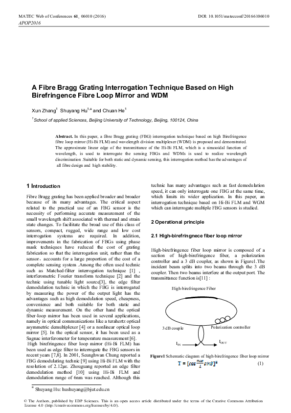
High-birefringence fiber loop mirror is composed of a
section of high-birefringence fiber, a polarization
controller and a 3 dB coupler, as shown in Figure1.The
incident beam splits into two beams through the 3 dB
coupler. Then two beams interfere at the output port. The
transmittance function is[11] :
High-birefringence Fiber
3 dB couple
IIN
Polarization controller
IOUT
Figure1 Schematic diagram of high-birefringence fiber loop mirror
(1)
Shuyang Hu: hushuyang@bjut.edu.cn
© The Authors, published by EDP Sciences. This is an open access article distributed under the terms of the Creative Commons Attribution
License 4.0 (http://creativecommons.org/licenses/by/4.0/).
�DOI: 10.1051/ matecconf/2016 610 6010
MATEC Web of Conferences 61, 06010 (2016)
APOP2016
The Hi-Bi FLM and WDM based FBG interrogation
system is carried out with the setup shown in Figure
3.The wide band light from SLED passes through
coupler1 and enter the sensing FBGs. The reflecting light
goes through coupler1 and is split into two beams via
coupler 2. One of the beam goes through Hi-Bi FLM and
WDM successively while the other beam only goes
through the other WDM the same as the first. Eventually
the light reflecting from different sensing FBGs is
separated into different optical detector. Via measuring
the corresponding beam going through FLM or not,
the transmittance ( ) of FBGs can be calculated out and
,the wavelength of FBGs can be determined.
where L is the length of HB fiber, ˨�is wavelength,
, is the difference of the index
along fast and slow axes, ˥�(is a certain constant when
Hi-Bi FLM having been installed )is the angle change of
the polarization of the light propagating through the fiber
, we get
,
loop, respectively. When
where
, ˂˨�and
is the wavelength range and
center wavelength of the source, respectively. We
simplify (1) as:
(2)
From (2), we know that the transmission of HiBi-FLM is
a sine function of ˨�with the period of
, which is
decided by L and B. The transmission of the f HiBi-FLM
we fabricated is shown in Figure 2, in which the curve A,
B and c is the spectrum of light source, the light
transmitting through the FLM and the transmittance,
respectively.
Figure 3 Schematic of the interrogation system
3 Experimental Results
In the experiment, CWDM is used to demonstrate the
technique whose transmission spectrum is shown in
Figure 4,in which P1 and P2 is the transmission spectrum
of port1 and port3,respectively.SLED is used as light
source and Hi-Bi FLM is made and the spectrum of them
are both shown in Figure.1. Two FBGs with the center
wavelength of 1520nm and 1550nm are used and the
spectrum of their reflecting light are shown in Figure 5.�
�
Figure2 The transmission spectrum of the Hi-Bi FLM
2.2 Interrogation principle
When the narrow band light reflecting by the FBG whose
spectrum band width is narrow comparing with the period
of transmission and its spectrum can be treated as
function is launched into HiBi- FLM, the intensity of
the light transmitted through is given by
(3)
Where and
is the intensity and wavelength of
reflected light of FBG, respectively. So, the transmittance
of the light reflectting from the sensing FBG and passing
through the Hi-Bi FLM can be given as
(4)
�
From (4) we know that we can interrogate the FBG by
measuring . Especially when the transmittance is in the
nearly linear range the Hi-Bi FLM can be treated as a
linear filter.
Figure 4 The spectrum of light
passing through the WDM
2
�DOI: 10.1051/ matecconf/2016 610 6010
MATEC Web of Conferences 61, 06010 (2016)
APOP2016
Figure 7 The schematic of wavelength
tuning of FBG using equal deform beam.
By tuning the weight the transmission (¨)varies with
wavelength shift and the relationship between them is
shown in Fig.8, with R2=0.9938.
Figure 5 The reflective spectrum of the FBGs
The reflecting light of FBGs go through Hi-Bi FLM and
WDM are separated into different detector and the two
spectrum of FBG1 and FBG2 are shown in one picture in
Figure 6. The wavelength of the FBGs can be
interrogated by the value of ¨ which can be calculated
by comparing the corresponding power of the light
passing through Hi-Bi FLM or not.
Figgure 8 Relationship between transmission
and wavelength of FBG1
4 Conclusions
In this paper, a FBG interrogation technique based on HiBi FLM and WDM is proposed and demonstrated. With
the capability of measure multiple FBG signal at the
same time based on WDM, the technique has the
advantages of fast demodulation, simple structure and
suitable for both static and dynamic measuring.
References
1.
Figure.6 The reflective spectrum of the FBGs
passing through WDM and Hi-Bi FLM
2.
We adhere FBG1 to the equal deform beam to tune it
which is shown in Figure 7. The beam is placed
horizontal with one end is fixed while the other is free. So,
we can tuning the wavelength of FBG by loading weight
to the free end.
3.
3
Davis M A , Kersey A D. Matched-filter
interrogation technique for fiber Bragg grating arrays
Electro. Lett, 1995, 31(10):822 ̚ 825
Ohn M M , Huang S Y , Measures R Mˈ et al..
Arbitrary strain profile measurement within fiber
gratings using interferometric Fourier transform
technique Electron. Lett ˈ 1997, 33(14):1242 ̚
1243
Br ady G , Kalli K , Webb D J, et alˈSimultaneous
interrogation of interferometric and Bragg grating
sensors Opt .Lett ., 1995, 20(11):1340 ̚ 1342
�DOI: 10.1051/ matecconf/2016 610 6010
MATEC Web of Conferences 61, 06010 (2016)
APOP2016
4.
5.
6.
7.
8.
J.P. Sokoloff, P.R. Prucnal, I. Glesk, and M. Kane, A
terahertz optical asymmetric demux (TOAD), IEEE
Photon Tech Lett 5 (1993), 787̢790.
N.J. Doran and D. Wood, Nonlinear-optical loop
mirror, Opt Lett 13 (1988), 56̢58.
A.N. Starodumov, L.A. Zenteno, D. Monzon, and E.
De La Rosa, Fiber Sagnac interferometer
temperature sensor, Appl Phys Lett 70 (1997),19̢
21.
MORTIMORE D B, Fiber loop reflectors J.
Lightwave Technol.ˈ1988ˈ6(7):1217-1224.
Zhou Guang, Zhao Qida, Liu Yange, et al., Filtering
Characteristics of fiber loop mirror filter composed
of multi-stage high birefringent fibers Acta Optica
Sinica 2004ˈ24(3):341-345.
9.
SEUNGHWAN CHUNGˈJUNGHO KIM, BONGAHN YUˈ et al., A Fiber Bragg Grating Sensor
Demodulation Technique Using a Polarization
Maintaining Fiber Loop Mirror IEEE Photonics
Technology Lettersˈ 2001ˈ3(2):1343-1346.
10. Zhou Guang, Zhao Qida,Kai Guiyun, et al., A novel
edge filter demodulation method using high
birefringence fiber loop mirror, Journal of
Optoelectronics Laser, 2003ˈ14(12):1245-1249.
11. Yange Liu, Bo Liu, Xinhuan Feng, et al, Highbirefringence fiber loop mirrors and their
applications as sensors, Applied Optics, 44(12):
2382-2390( 2005)}
4
�
 Orlando Frazão