Academia.edu no longer supports Internet Explorer.
To browse Academia.edu and the wider internet faster and more securely, please take a few seconds to upgrade your browser.
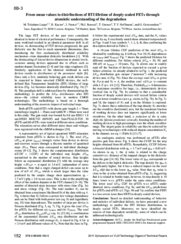
From mean values to distributions of BTI lifetime of deeply scaled FETs through atomistic understanding of the degradation
From mean values to distributions of BTI lifetime of deeply scaled FETs through atomistic understanding of the degradation
 Philippe J . Roussel
2011
Related Papers
IEEE International Reliability Physics Symposium Proceedings
Origin of NBTI variability in deeply scaled pFETs2010 •
IEEE Transactions on Electron Devices
Statistical Simulation of Progressive NBTI Degradation in a 45-nm Technology pMOSFET2000 •
2010 •
Abstract-The statistical distribution of negative bias temperature instability (NBTI) in deca-nanometer p-channel FETs is discussed. An exponential distribution of threshold voltage shifts due to a single charge trapped in the gate oxide is observed, resulting in single-charge shifts exceeding 30 mV in some of the studied 35-nm-long and 90-nm-wide devices. The exponential distribution is justified with a simple channel percolation model. Combined with the assumption of the Poisson-distributed number of trapped gate oxide charges, an analytical description of the total NBTI threshold voltage shift distribution is derived. This allows, among other things, linking its first two moments with the average number of defects per device, which is found < 10 in the studied devices. Index Terms-MOSFETs, negative bias temperature instability (NBTI), reliability, variability.
2010 •
The Scientific World Journal
Effects of Gate Stack Structural and Process Defectivity on High- k Dielectric Dependence of NBTI Reliability in 32 nm Technology Node PMOSFETs2014 •
We present a simulation study on negative bias temperature instability (NBTI) induced hole trapping inE′center defects, which leads to depassivation of interface trap precursor in different geometrical structures of high-kPMOSFET gate stacks using the two-stage NBTI model. The resulting degradation is characterized based on the time evolution of the interface and hole trap densities, as well as the resulting threshold voltage shift. By varying the physical thicknesses of the interface silicon dioxide (SiO2) and hafnium oxide (HfO2) layers, we investigate how the variation in thickness affects hole trapping/detrapping at different stress temperatures. The results suggest that the degradations are highly dependent on the physical gate stack parameters for a given stress voltage and temperature. The degradation is more pronounced by 5% when the thicknesses of HfO2are increased but is reduced by 11% when the SiO2interface layer thickness is increased during lower stress voltage. However...
Facta universitatis - series: Electronics and Energetics
NBT stress and radiation related degradation and underlying mechanisms in power VDMOSFETsIEEE Transactions on Electron Devices
Interplay Between Statistical Variability and Reliability in Contemporary pMOSFETs: Measurements Versus Simulations2014 •
Issues in Ethnology and Anthropology
Nevidljivo nasleđe: stari Egipat i muzeji u Srbiji2018 •
Muzejske zbirke Srbije, uz jednu mumiju i dva kovčega, raspolažu sa tek nešto više od sto pedeset staroegipatskih artefakata koji su stečeni pretežno krajem XIX i početkom XX veka i to kao pokloni, a samo je jedan skarabej pronađen tokom arheoloških iskopavanja u našoj zemlji. Staroegipatske starine iz naših muzeja, skoro bez izuzetka sve već stručno i naučno obrađene i publikovane, javnosti su već dugo nedostupne ili ih samo povremeno može videti ograničeni broj posetilaca (deo zbirke beogradskog Narodnog muzeja u Arheološkoj zbirci Filozofskog fakulteta). Ne pominju ih ni internet prezentacije muzeja koji čuvaju njihov najveći deo, tj. prezentacije muzeja u Vršcu, Beogradu i Somboru. Biće razmotreni potencijalni razlozi za takvu „nevidljivost“, a posebno pitanja da li su te starine percipirane kao nasleđe, u kakvu se kategoriju nasleđa svrstavaju i kakvi kriterijumi na to utiču.
RELATED PAPERS
La natura della montagna
Carte e plans-reliefs militari francesi di metà Ottocento Riflessioni intorno alla rappresentazione della vegetazione2013 •
Spisy Filozofické fakulty Masarykovy univerzity
Břeclav – Pohansko VII. Kostelní pohřebiště na Severovýchodním předhradí / Břeclav - Pohansko VII. The Church Cemetery in the North-eastern Suburb - FULL TEXT for download2016 •
Journal of Solid State Chemistry
Tauc-plot scale and extrapolation effect on bandgap estimation from UV–vis–NIR data – A case study of β-Ga2O32020 •
2007 •
British Journal of Educational Technology
Educational technology research trends in Turkey from a critical perspective: An analysis of postgraduate theses2019 •
2017 •
International Journal of E-Business Research
An Approach to Aggregate the Partial Rank List of Web Services in E-Business2019 •
2019 •
Powder Diffraction
C-1 XRF and XRD Analysis of Converted Lead Pigment on a Georgia O'Keefe Pastel Drawing2008 •
Optical Engineering
Review of nonlinear ultrasonic guided wave nondestructive evaluation: theory, numerics, and experiments2015 •
Ecological Applications
Floodplain restoration enhances denitrification and reach‐scale nitrogen removal in an agricultural stream2012 •
Proceedings on Engineering Sciences
TOTAL QUALITY MANAGEMENT INTEGRATED STRATEGY: ITS IMPLICATION TO ORGANIZATIONAL SUCCESS2022 •
RELATED TOPICS
- Find new research papers in:
- Physics
- Chemistry
- Biology
- Health Sciences
- Ecology
- Earth Sciences
- Cognitive Science
- Mathematics
- Computer Science