Academia.edu no longer supports Internet Explorer.
To browse Academia.edu and the wider internet faster and more securely, please take a few seconds to upgrade your browser.
Power quality improvement and mitigation case study using distributed power flow controller
Power quality improvement and mitigation case study using distributed power flow controller
Power quality improvement and mitigation case study using distributed power flow controller
Power quality improvement and mitigation case study using distributed power flow controller
Power quality improvement and mitigation case study using distributed power flow controller
 Masoud Barakati
2012, 2012 IEEE International Symposium on Industrial Electronics
Related Papers
International Journal of Engineering Research and Technology (IJERT)
IJERT-A New Distributed Power Flow Controller to Improve the Power Quality by Mitigating Voltage Sag and Swell2013 •
https://www.ijert.org/a-new-distributed-power-flow-controller-to-improve-the-power-quality-by-mitigating-voltage-sag-and-swell https://www.ijert.org/research/a-new-distributed-power-flow-controller-to-improve-the-power-quality-by-mitigating-voltage-sag-and-swell-IJERTV2IS90587.pdf Now-a-days the power demanded by different consumers is much higher than the past days. This demand is due to the increased usage of electric power for different types of loads in balanced and unbalanced conditions. When the load on the consumer side is unbalanced, the current will flow through the neutral wire. Hence due to I 2 R losses voltage drop will occur in neutral. As a result the quality of distribution of power gets decreases. In order to improve the quality of power different techniques are adopted. Voltage sag and swell of the power quality issues are studying and the quality of power can be increased by using a FACTS device called Distributed Power Flow Controller (DPFC). This is used to mitigate the voltage deviation and improve power quality. The structure of this device is similar to that of UPFC (Unified Power Flow Controller), in spite the common dc-link between the shunt and series converters is eliminated and three-phase series converter is divided to several single-phase series distributed converters through the line.The operation and the control of DPFC which is connected to a single-machine infinite bus power system including two parallel transmission lines, the analysis is calculated/simulated in MATLAB/Simulink environment to improve the quality of power.
Modern power utilities have to respond to a number of challenges such as growth of electricity demand specially in non-linear loads in power grids, consequently, That higher power quality should be considered. In this paper, DPFC which is similar to unified power flow controller (UPFC) in structure, which is used to mitigate the voltage sag and swell as a power quality issue. Unlike UPFC, the common dc-link in DPFC, between the shunt and series converter devices should be eliminated and three-phase series converter is divided to several single-phase series distributed converters through the power transmission line. And also to detect the voltage sags and find out the three single-phase reference voltages of DPFC, the synchronous reference frame method is proposed. Application of DPFC in power quality enhancement is simulated in Mat lab/Simulink environment which show the effectiveness of the proposed structure
International Journal of Engineering Research and Technology (IJERT)
IJERT-Comparison of the Performance of Distributed Power Flow Controller and Distributed Interline Power Flow Controller Facts Controllers in Power System2014 •
https://www.ijert.org/comparison-of-the-performance-of-distributed-power-flow-controller-and-distributed-interline-power-flow-controller-facts-controllers-in-power-system https://www.ijert.org/research/comparison-of-the-performance-of-distributed-power-flow-controller-and-distributed-interline-power-flow-controller-facts-controllers-in-power-system-IJERTV3IS111052.pdf This paper describes the power flow control in transmission line with Flexible AC Transmission System (FACTS) family, called Distributed Power Flow Controller (DPFC) and Distributed Interline Power Flow Controller (DIPFC). The DPFC is derived from the Unified Power Flow Controller (UPFC). The DPFC can be considered as UPFC with an eliminated common DC link, to enable the independent operation of the shunt and the series converters which enhances the effective placement of the series and shunt converters. The active power exchange between the two converters, which is through the common dc link in the UPFC, is now through the transmission lines at the third-harmonic frequency in the DPFC & DIPFC. DPFC & DIPFC is used to mitigate the voltage sag and swell as a power quality issue. The DPFC and DIPFC has the same control capability as the UPFC, which comprises the adjustment of the line impedance, the transmission angle, and the bus voltage. In DPFC three-phase series converter is divided to several single-phase series distributed converters through the transmission line and in DIPFC three single phase series converters are placed in between the two transmission lines. Modelling and principle of operation is presented in this paper. To verify the DPFC principle two case studies are considered. Case (i) DPFC is placed in a single-machine infinite bus power system including two parallel transmission lines. Case (ii) Distributed Interline Power Flow Controller (DIPFC) is placed between the two parallel transmission lines of infinite bus. The case studies are simulated in MATLAB/ Simulink and the results validate the DIPFC has ability to improve the power quality then DPFC.
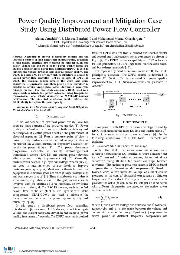
According to growth of electricity demand and the increased number of non-linear loads in power grids, providing a high quality electrical power should be considered. In this paper, voltage sag and swell of the power quality issues are studied and distributed power flow controller (DPFC) is used to mitigate the voltage deviation and improve power quality. The DPFC is a new FACTS device, which its structure is similar to unified power flow controller (UPFC). In spite of UPFC, in DPFC the common dc-link between the shunt and series converters is eliminated and three-phase series converter is divided to several single-phase series distributed converters through the line. The case study contains a DPFC sited in a single-machine infinite bus power system including two parallel transmission lines, which simulated in MATLAB/Simulink environment. The presented simulation results validate the DPFC ability to improve the power quality.
International Journal of Engineering Research and Technology (IJERT)
IJERT-Voltage Sag and Swell Mitigation Using DPFC and Improve Power Quality2013 •
https://www.ijert.org/voltage-sag-and-swell-mitigation-using-dpfc-and-improve-power-quality https://www.ijert.org/research/voltage-sag-and-swell-mitigation-using-dpfc-and-improve-power-quality-IJERTV2IS110057.pdf Modern power utilities have to respond a no.of challenges such as growth of electricity demand specially non-linear loads in power grids consequently some high quality electrical power should be considered. The DPFC is a new FACT device. In this work DPFC considered as a UPFC with an eliminated common dc link and it is used to mitigate the voltage sag and swell and improve power quality. The active power exchange between the shunt and series converters which is through the common dc link in the UPFC is now through the Transmission lines at the third harmonic frequency. Accordingly the cost of the DPFC system is lower than the UPFC. The DPFC has the same control capability as the UPFC which comprises the adjustment of the line impedance, transmission angle and bus voltage. Which is simulated in Matlab/Simulink environment and the corresponding results will be shown.
2018 •
A new control scheme to improve and maintain the power quality of an electrical power system is distributed power flow controller (DPFC).The DPFC is derived from the unified power-flow controller (UPFC). The DPFC can be considered as a UPFC with an eliminated common dc link. The active power exchange between the shunt and series converters which is through the common dc link in the UPFC is now through the transmission lines at the third-harmonic frequency. In DPFC the common link between shunt converter and series converter is eliminated and instead of three phase series converter several single phase distributed series converters are modeled. The large number of series converters provides redundancy, thereby increasing the system reliability. Nowadays there is growth in Electricity demand and increase in non-linear load causes the major power quality problems like harmonics voltage sag and swell in power grid. Experimental results are carried out in MATLAB/Simulink.
Volume 1, Issue 9
Enhancement of Power Quality by Multi – Connected Distributed Power Flow Controller (MC-DPFC)This paper presents a new component within the Flexible AC Transmission System (FACTS) family, called Distributed Power Flow Controller (DPFC) capable of simultaneous compensation for the voltage and current in multi bus system. DPFC is derived from the UPFC with an eliminated common DC link. In this configuration one shunt voltage source converter and two or more series voltage source converters exist. The system can be applied to adjacent feeders to compensate for supply-voltage and load current imperfections on the main feeder. The active power exchange between the shunt and series converters, which is through the common dc link in the UPFC, is now through the transmission lines at the third-harmonic frequency. The DPFC can be designed with multiple single phase series converters (DFACTS) and one three phase shunt converter. The reliability of the DPFC system is further improved by the use of multiple single phase series converters with the adapted control schemes. The DPFC having much control capability like UPFC, however at much reduced cost and an improved reliability. The DPFC has the same control capability as the UPFC, which comprises the adjustment of the line impedance, the transmission angle, and the bus voltage. The principle and analysis of the DPFC are presented. The case study contains a DPFC sited in a single-machine infinite bus power system including two parallel transmission lines, which simulated in MATLAB/ Simulink and the results validate the DPFC ability to improve the power quality
2020 •
This paper describes a new component in FACTS Technology, named as the Distribution Power Flow Controller (DPFC), which is originated from the Unified Power Flow Controller (UPFC) with an elimination of the DC link between the shunt and series converters. Hence, the three-phase series converter is segregated into several single-phase series distributed converters through the line. The large number of series converters provide redundancy, thereby increasing the system reliability. The study contains the simulation of a single machine infinite bus power system including two parallel transmission lines, in MATLAB/Simulink environment. The simulated results present that the power quality issues such as voltage sag and swell are mitigated, validating the DPFC ability to improve the power quality.
This paper presents the mitigation of voltage sag and swells in Distributed Power Flow Controller (DPFC). The DPFC is the next generation of Unified Power-Flow Controller (UPFC). The DPFC can be considered as a UPFC with an eliminated common dc link. The active power exchange between the shunt and series converters, which is through the common dc link in the UPFC, is now done through the transmission lines. In DPFC many single phase converters are used instead of one three phase converter. The cost of the DPFC system is lower. Here, the capability of DPFC is observed for the transmission line based on Ant Colony Optimization (ACO). Based on the performance, we can say that ant colony optimization based DPFC gives better compensation than other Controller based DPFC. Matlab/Simulink is used to create the Ant Colony Optimization and FLC and to simulate DPFC model.
RELATED PAPERS
International Journal of Computer Applications
A Literature Review on the Unified Power Flow Controller UPFC2018 •
International Journal of Engineering Research and Technology (IJERT)
IJERT-Performance Analysis of 72-Pulse GTO-based Generalized unified Power Flow Controller Under Power Quality Problems2021 •
2020 •
International Journal of Engineering Research and Technology (IJERT)
IJERT-Distributed Power-Flow Controller for Enhancing Power System Stability2013 •
2021 •
International Journal of Electrical and Electronic Engineering & Telecommunications
A Review of Fuel Cell to Distribution Network Interface Using D-FACTS: Technical Challenges and Interconnection Trends2013 •
IAEME PUBLICATION
Power Flow Control by Using D-FACTS Concept Through DPFC2015 •
2017 •
Shraddha Bele | Pratik Ghutke
Generalized Unified Power Quality Conditioner UPQC System with an Improved Control Method Under Distorted and Unbalanced Load Conditions2019 •
IEEE Transactions on Power Electronics
A FACTS Device: Distributed Power-Flow Controller (DPFC)2000 •
2012 13th International Conference on Optimization of Electrical and Electronic Equipment
Control of distributed power flow controllers using active power from homopolar line currents2012 •
International Journal of Engineering Research and Technology (IJERT)
IJERT-Modelling Of Distributed Power Flow Controller (DPFC) Using Matlab/Simulation2013 •