Full Paper
Confinement Effect on the
Body-Centered-Cubic Phase of Diblock
Copolymers in Film
Hongge Tan,* Qinggong Song, Shuang Yang, Dadong Yan,* An-Chang Shi
In this paper, we study the morphology of diblock copolymers with the body-centered-cubic
(bcc) phase confined between two flat surfaces. Employing the Landau–Brazovskii mean field
theory and the single mode approximation, we obtain three amplitude parameters as
functions of temperature, surface field strength, and film thickness. Because of the effect
of confinement size and the surface inducement, the morphology of confined diblock copolymers is different from the bulk structure. By
controlling confinement size and surface field
strength, lamella, undulated lamella, cylinder,
and distorted cylinder can be observed in the
bcc bulk phase of diblock copolymers. Also, we
construct a ‘‘phase diagram’’ of confinementinduced structures at different surface field
strengths. We compare the present theoretical
results with the other relevant theoretical results.
The predictions about these interesting confinement-induced structures should be observable in
the experiments under suitable conditions.
Introduction
The self-assembly of diblock copolymers has drawn more
and more attention because of the rich ordered microstructures.[1–6] The ordered microstructures can be applied
H. Tan, Q. Song
College of Science, Civil Aviation University of China,
Tianjin 300300, China
E-mail: thg@iccas.ac.cn
S. Yang, D. Yan
State Key Laboratory of Polymer Physics and Chemistry, Institute
of Chemistry, Chinese Academy of Sciences, Beijing 100080,
China
E-mail: yandd@iccas.ac.cn
A.-C. Shi
Department of Physics and Astronomy, McMaster University,
Hamilton, Ontario L8S 4M1, Canada
Macromol. Theory Simul. 2008, 17, 45–51
ß 2008 WILEY-VCH Verlag GmbH & Co. KGaA, Weinheim
in nanotechnology.[7,8] For bulk diblock copolymers,
lamellae, hexagonal arrays of cylinders, body-centeredcubic (bcc) arrays of spheres, and the bicontinuous gyroid
have been obtained in turn by changing the interactions
between the distinct blocks and architectures of those
blocks.[1–6] A good understanding of the bulk phase behavior has been obtained. For diblock copolymers confined
by the environment of a system, the self-assembly process
is more complicated and interesting due to the confinement geometry and the interactions between the block
copolymer and the surface. The self-assembly in confined
environment is a new approach toward preparing ordered
periodic nanostructured materials and has attracted
considerable interest in recent years.[7–31]
Much attention has been focused on the self-assembly
of symmetric diblock copolymers in a confined environment.[9–18] Their phase behavior has been understood
DOI: 10.1002/mats.200700064
45
�H. Tan, Q. Song, S. Yang, D. Yan, A.-C. Shi
fairly well. For confined asymmetric block copolymers
with cylindrical bulk morphology, some studies have also
been carried out theoretically[19–23] and experimentally.[24–27] Under confinement, diblock copolymers with
cylindrical bulk phase cannot only change the orientation
of cylinders, but also alternate between different morphologies.
In contrast to the lamellar bulk phase and the cylindrical
bulk phase, confined diblock copolymers with the spherical bulk phase receive less attention. Although a few
papers appeared which deal with some aspects of the bcc
phase in thin film, the emphases of these papers are
different from that of our work.[28–31] Recently, we studied
theoretically the surface effect on the bcc spherical bulk
phase.[32] As a continuation of the previous study,[32] in
this paper, we devote to the confinement effect on the bcc
forming asymmetric diblock copolymers under the interactions between surfaces and diblock copolymers.
This paper is organized as follows. In the next section, in
weak segregation limit we induce the model in which the
diblock copolymer melt with bcc bulk phase is confined
between two flat surfaces with surface interaction. In the
subsequent section, we study the structure evolution
under different film thicknesses and different surface field
strengths. The corresponding discussions are also given in
this section. In the last section, we give the conclusions.
Theory
As a continuation of the previous study, the model we
describe here is the same as that in ref.[32] We consider an
incompressible melt of n AB diblock copolymers in a
volume V0 at a temperature T. The total degree of polymerization of the diblock copolymer is N. The degree of
polymerization of the A block is fAN, where fA is the
fraction of segments on each chain that are of type A.
The effective interaction between statistical segments of
type A and type B is characterized by the dimensionless Flory–Huggins parameter x in kBT units. The order
parameter of diblock copolymers is defined as
fðrÞ � fA ðrÞ � fA , the deviation of the local A monomer
concentration from its average value. In the weak
segregation regime, the Landau–Brazovskii model can be
used. Specifically, the Landau–Brazovskii free energy per
block copolymer f ½fðrÞ� is given by
f ½fðrÞ� ¼
1
V
Z
dr
� 2
�
j
t
g
1
½ðr2 þ 1Þf�2 þ f2 � f3 þ f4
2
2
3!
4!
(1)
Here, the details of the parameters in Equation (1) can be
found in ref.[1–3] and[32–34]. j and g are functions of fA; t is a
46
Macromol. Theory Simul. 2008, 17, 45–51
ß 2008 WILEY-VCH Verlag GmbH & Co. KGaA, Weinheim
function of xN and fA. When xN ¼ xNs (the disorder to order
spindal point), t ¼ 0. In the weak segregation limit, fA
and xN are chosen close to the order–disorder critical
temperature. For a bcc structure in the weak segregation
regime, it is sufficient to restrict ourselves to the first mode
in the reciprocal space with the reciprocal lattice vectors
pffiffiffi
~ i j ¼ q0 ¼ 2p=ðb= 2Þ (b is the lattice parameter and
jG
~ i j ¼ 1 in scaled units), instead of using the complete set
jG
~ i . In the single mode approximation, the bulk
of vectors G
bcc spherical phase can be described by the order
parameter (see Equation (16) in ref.[32])
~ 1 � rÞ þ 2a2 ðrÞ½cosðG
~ 2 � rÞ
fðrÞ ¼ 2a1 ðrÞ cosðG
~
~
þ cosðG3 � rÞ� þ 2a3 ðrÞ½cosðG4 � rÞ
~ 5 � rÞ þ cosðG
~ 6 � r�
þ cosðG
(2)
with
~1
G
~2
G
~3
G
~
G4
~5
G
¼ z^; pffiffiffi
¼ 12 ð 3x^ þ z^Þ;
pffiffiffi
¼ 12 ð� 3x^ þ z^Þ;
pffiffiffi
¼ p1ffiffi3 ðx^ þ 2y^Þ;
pffiffiffi
pffiffiffi
¼ 2p1 ffiffi3 ðx^ � 2 2y^ þ 3z^Þ;
pffiffiffi
pffiffiffi
~ 6 ¼ p1 ffiffi ð�x^ þ 2 2y^ þ 3z^Þ
G
2 3
where a1 (r), a2 (r), and a3 (r) are space-dependent
amplitude functions describing the variation of microstructures. In the bcc bulk melt, a1 ¼ a2 ¼ a3 ¼ abcc, with
which the order parameter describes bcc spheres. Furthermore, when a1 ¼ a2 ¼ ahex and a3 ¼ 0, the order parameter
describes the hexagonal arrays of cylinders. When
a1 ¼ alam and a2 ¼ a3 ¼ 0, the order parameter describes
the lamellae.
When the diblock copolymer melt is put in contact with
two flat surfaces, the translational symmetry is broken. In
order to study the confinement-induced structures in the
bcc spherical phase explicitly under interactions between
polymers and the surfaces, we choose surface plane as the
z ¼ 0 and z ¼ l planes and assume that the surface is
presented by a surface potential. Thus, the free energy of
the system is given by
V¼
1
V
Z
drðf�fðrÞDu½dðzÞ þ dðz � lÞ�g þ f ½fðrÞ�Þ
(3)
Du is the differential affinity of surface tensions with
respect to one block of the copolymer.[21] If uAS and uBS are
the surface tensions of polymers A and B with respect to
the surface, one has Du ¼ uBS � uAS . By uAS and uBS, Du can
be related to any available material. d(z) and d(z � l) are
delta functions, which mean that the interactions are short
range and only exist on the surfaces (z ¼ 0 plane and z ¼ l
plane). We assume that the amplitudes a1, a2, and a3 are
only z-dependent, and vary slowly on the scale of l0, which
DOI: 10.1002/mats.200700064
�Confinement Effect on the BCC Phase of Diblock Copolymers . . .
is the characteristic period of the lamellar component in
the bulk melt. Also, we neglect the effect of the incommensurability between l and l0, although this incommensurability affects the orientation on the
microstructure, which is the result of the competition
between the surface interaction and the incommensurability. Under the above two assumptions, we can separate
the length scale for variations in the amplitude from the
length scale of the microstructure. Since we have assumed
the amplitudes vary slowly on the scale of l0, we only
retain gradient terms up to quadratic order in the
Landau–Brazovskii free energy. Thus the free energy per
unit surface can be written as (see Equation (26) in ref.[32])
~ ¼ �sXð0Þ � sXðLÞ
V
!2
� �
� �
Z L (
dX
1 dY 2 1 dZ 2
dt
þ
þ
þ
dt
2 dt
2 dt
0
)
þ f ½XðtÞ; YðtÞ; ZðtÞ�
values of s ¼ 0.9 and 2 corresponding to weaker and
stronger surface fields, respectively, as we did in ref.[32]
Results and Discussion
In this section, we show that how the film thickness affects
the bulk structure under different surface field strengths.
As the first step, we linearize the free energy of bulk phase
f(X, Y, Z) around the bcc structure. Minimizing the total free
energy given by Equation (4), we obtain three linear
Euler–Lagrange equations. Under the boundary conditions,
we obtain the general solutions of these linear equations,
DXðtÞ ¼ XðtÞ � Xbulk
¼s
3 h
i
X
CXi ða; LÞe�li ðaÞt þ CXiþ3 ða; LÞeli ðaÞt
i¼1
(5)
ð4Þ
DYðtÞ ¼ YðtÞ � Ybulk
with
X ¼ a1 =g;
t ¼ zg=2j;
s ¼ Du=jg 2 ;
Y ¼ a2 =g;
L ¼ lg=2j;
~ ¼ V=2jg 3
V
Z ¼ a3 =g;
Here, the parameters g and j can be determined by
f(X, Y, Z) is the free energy of the bulk diblock
fA.
copolymers and the expression can be found in ref.[32] Thus
X(t), Y(t), and Z(t) are related to the variation of the
structures since they are proportional to a1(z), a2(z), and
a3(z), respectively. The reduced distance t, the effective film
thickness L and the reduced surface field strength s are
used instead of z, the film thickness l and Du which can be
obtained from the experiments, respectively. Minimizing
the free energy in Equation 4, we obtain three-coupled
Euler–Lagrange equations for the amplitudes of X(t), Y(t),
and Z(t). The formation of these three Euler–Lagrange
equations are the same as Equation (27)–(29) in ref.[32]
From Equation 4, we can obtain the boundary conditions
�
�
dX ��
dX ��
¼ � � ¼ �s
dt �t¼0
dt t¼L
¼s
In the following section, we can solve these threecoupled Euler–Lagrange equations and discuss the results
with the parameters L, s and effective temperature a,
which appears in f (X, Y, Z) and is defined as t/g 2 in ref.[32]
Although we cannot relate these values to any available
materials at the moment, we can still select two typical
Macromol. Theory Simul. 2008, 17, 45–51
ß 2008 WILEY-VCH Verlag GmbH & Co. KGaA, Weinheim
(6)
i¼1
DZðtÞ ¼ ZðtÞ � Zbulk
[1–3,32,34]
�
�
�
�
dY ��
dY ��
dZ ��
dZ ��
¼
¼
¼
¼0
dt �t¼0
dt �t¼L dt �t¼0 dt �t¼L
3 h
i
X
CYi ða; LÞe�li ðaÞt þ CYiþ3 ða; LÞeli ðaÞt
¼s
3 h
i
X
CZi ða; LÞe�li ðaÞt þ CZiþ3 ða; LÞeli ðaÞt
(7)
i¼1
where CXi(a, L), etc. are the coefficients of the solutions of
the linear equations and are determined by a and L.
In order to study the confinement effect, first we fix the
effective interaction s ¼ 0.9 and the effective temperature
a ¼ �0.02 (far from the effective transition temperature
a� ¼ �0:07345, as mentioned in ref.[32]). We obtain
Xbulk ¼ Ybulk ¼ Zbulk ¼ 0.27613,[32] l1 ¼ 1.7046, l2 ¼ 1.1034,
and l3 ¼ 0.5997. We change the film thickness and consider
three different cases as follows.
The first case is for a thick film in which we choose
L ¼ 12. In this case, by solving the linear Euler–Lagrange
equations, the corresponding coefficients are CX1 ¼
2.783 � 10�3, CX2 ¼ 0.1104, CX3 ¼ 1.457, CX4 ¼ 3.638 �
10�12, CX5 ¼ 1.962 � 10�7, CX6 ¼ 1.091 � 10�3, CY1 ¼ 3.268 �
� 10�2, CY2 ¼ �0.3496, CY3 ¼ 0.5507, CY4 ¼ 4.271 � 10�11,
CY5 ¼ �6.212 � 10�7, CY6 ¼ 4.124 � 10�4, CZ1 ¼ 4.671 � 10�2,
CZ2 ¼ 0.2314, CZ3 ¼ �0.5589, CZ4 ¼ 6.105 � 10�11, CZ5 ¼
4.112 � 10�7, and CZ6 ¼ �4.186 � 10�4. These asymptotic
solutions can be used as the initial conditions to obtain the
exact numerical solutions of three Euler–Lagrange equations and then we obtain the amplitudes X(t), Y(t), and Z(t)
varying with t. The results are shown in Figure 1. On the
surfaces, Y ¼ 0.208 and Z ¼ 0.005, which indicate the
www.mts-journal.de
47
�H. Tan, Q. Song, S. Yang, D. Yan, A.-C. Shi
Figure 1. Reduced amplitudes X(t), Y(t), and Z(t) as functions of t
for a ¼ �0.02, s ¼ 0.9, and L ¼ 12.
Figure 3. Reduced amplitudes X(t), Y(t), and Z(t) as functions of t
for a ¼ �0.02, s ¼ 0.9, and L ¼ 1.
cylindrical component exists and the spherical component
is negligible.
The second case is for the medium thickness film,
in which we choose L ¼ 6. In this case, the corresponding coefficients are CX1 ¼ 2.783 � 10�3, CX2 ¼ 0.1106,
CX3 ¼ 1.497, CX4 ¼ 1.006 � 10�7, CX5 ¼ 1.474 � 10�4, CX6 ¼
0.0410, CY1 ¼ 3.268 � 10�2, CY2 ¼ �0.3501, CY3 ¼ 0.5658,
CY4 ¼ 1.181 � 10�6, CY5 ¼ �4.667 � 10�4, CY6 ¼ 1.548 �
10�2, CZ1 ¼ 4.671 � 10�2, CZ2 ¼ 0.2317, CZ3 ¼ �0.5742,
CZ4 ¼ 1.689 � 10�6, CZ5 ¼ 3.089 � 10�4, and CZ6 ¼ �1.571 �
10�2. Following the same process as above, we obtain the
amplitudes X(t), Y(t), and Z(t) varying with t. The results are
shown in Figure 2. On the surfaces, Y ¼ 0.191 and
Z ¼ 0.0008, which are smaller than those in the first case
and indicate the cylindrical component still exists while
the spherical component is nearly negligible. Furthermore,
all the values of Z(t) are almost zero, which means that the
spherical component hardly exists throughout the whole
film.
The third case is for a thin film, in which we choose L ¼ 1.
In this case, the corresponding coefficients are CX1 ¼
3.402 � 10�3, CX2 ¼ 0.1652, CX3 ¼ 3.229, CX4 ¼ 6.186 � 10�4,
CX5 ¼ 5.482 � 10�2, CX6 ¼ 1.772, CY1 ¼ 3.994 � 10�2, CY2 ¼
�0.5232, CY3 ¼ 1.220, CY4 ¼ 7.263 � 10�3, CY5 ¼ �1.736,
CY6 ¼ 0.6698, CZ1 ¼ 0.0571, CZ2 ¼ 0.3462, CZ3 ¼ �1.238,
CZ4 ¼ 1.038 � 10�2, CZ5 ¼ 0.1149, and CZ6 ¼ �0.6797. We
also obtain the amplitudes X(t), Y(t), and Z(t) varying with t
shown in Figure 3. Note that all the values of Y(t) and Z(t)
become negligible, which indicate that the cylindrical
component and the spherical component disappear in the
film.
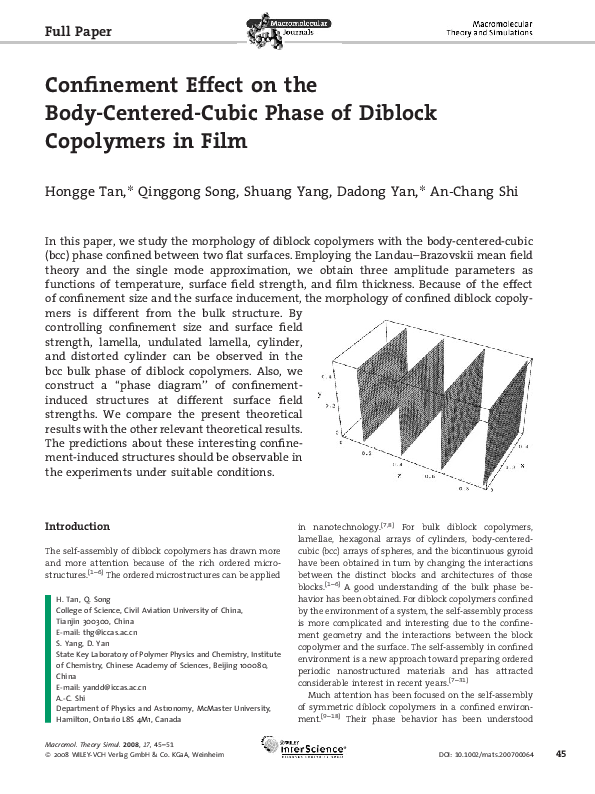
To demonstrate the evolution of the confinementinduced structures explicitly, the real space profiles of
the system are presented in Figure 4–6 for L ¼ 12, 6, and 1,
respectively. From Figure 4, we find that when L is large,
the structures in the film change from undulated lamellae
near the surfaces to cylindrical structures, then to the
distorted cylindrical structures, and finally to the spherical
structures near the center of the thin film. From Figure 5,
we can find that the spherical structures disappear, and
cylindrical structures appear near the center of the film
and then convert to undulated lamellar structures near the
surfaces. Figure 6 shows that when L is small enough,
lamellar phases extend throughout the film.
The results for s ¼ 2 are only quantitatively different
from those for s ¼ 0.9. To save space, we do not present the
results here. In order to illustrate the structure variation
with film thickness, we construct a phase diagram for
a ¼ �0.02 with s ¼ 0.9 and 2, respectively, as shown in
Figure 7. Lines L1 and L2 describe the positions where the
amplitudes Y(t) reach 10% of X(t) from the surfaces
(t ¼ 0 and L) for s ¼ 0.9 and 2, respectively. To the right of
Figure 2. Reduced amplitudes X(t), Y(t), and Z(t) as functions of t
for a ¼ �0.02, s ¼ 0.9, and L ¼ 6.
48
Macromol. Theory Simul. 2008, 17, 45–51
ß 2008 WILEY-VCH Verlag GmbH & Co. KGaA, Weinheim
DOI: 10.1002/mats.200700064
�Confinement Effect on the BCC Phase of Diblock Copolymers . . .
Figure 4. Three-dimensional contour plot of the order parameter fðx; y; zÞ in the region with amplitudes from the solid lines in Figure 1. z is
taken as t (in length unit of q�1
0 ¼ 4p).
these lines, the cylindrical components begin to be
appreciable. Lines C1 and C2 describe the positions where
the amplitudes Z(t) reach 10% of X(t) for s ¼ 0.9 and 2,
respectively. To the right of these lines, the spherical
components begin to appear.
From Figure 7 one can find that the effect of confinement for weaker and stronger surface field are different.
The region where the lamellar phase exists for s ¼ 0.9 is
smaller than that for s ¼ 2. The critical thickness Lc1 for
s ¼ 0.9, below which the lamellar phases extend throughout the film, is smaller than Lc2 for s ¼ 2. It is because the
stronger surface field strength can induce lamellar phases
easily.
The structures in the confinement film are different
from those in ref.[32] First, the main difference comes from
the cusp of lines L1, L2, C1, and C2. According to ref.,[32] these
lines should always keep the same distances from the
surfaces (t ¼ 0 and L) and intersect directly at a point which
is in front of the cusp of the lines in Figure 7. This can be
considered as the effect of confinement. Secondly, the
values of Y(t) and Z(t) near the surface decrease with a
decrease in the film thickness (see Figure 1–3), which
indicates that the cylindrical component exists for thicker
films and then disappears little by little near the boundary
with the decrease in the film thickness. Finally, the
lamellar phase appears in a thin enough film even for a
weaker surface field. This means that the confinement
makes the lamellar phase appear for a weaker surface field.
In other studies, Pereira also proved that the cubic to
cylindrical transition was possible in diblock copolymers
confined in the thin film.[28] His theoretical analysis was
carried out in the strong segregation limit and confining
Figure 5. Three-dimensional contour plot of the order parameter fðx; y; zÞ in the region with amplitudes from the solid lines in Figure 2.
Macromol. Theory Simul. 2008, 17, 45–51
ß 2008 WILEY-VCH Verlag GmbH & Co. KGaA, Weinheim
www.mts-journal.de
49
�H. Tan, Q. Song, S. Yang, D. Yan, A.-C. Shi
Figure 6. Three-dimensional contour plot of the order parameter fðx; y; zÞ in the region with amplitudes from the solid lines in Figure 3.
plates were neutral with respect to each block, which
disagreed with our theoretical work. He predicted that the
cylindrical phase should appear in thin films and the bcc
phase should be observed in thicker film. The conclusion
there is in agreement with some of the present results.
Therefore, our work and Pereira’s work should be seen as
complementary to each other. Tsori reported that the
external electric fields could be used to induce a phase
transition from the bcc spheres to the hexagonal array of
cylinders, which also proves indirectly the present results
are reasonable.[29] Till date, a systematic experimental
study of the evolution of confinement-induced structures
in bcc spherical phase of diblock copolymers was lacking.
We expect that the present prediction should be observable under appropriate experimental conditions.
Conclusion
Figure 7. Phase diagram, i.e., reduced film thickness L versus
reduced distance t, for a ¼ �0.02 with s ¼ 0.9 (solid lines) and
2 (dashed lines), respectively. Lines L1 and L2 describe the positions
where the amplitudes Y(t) reach 10% of X(t) from the surfaces
(t ¼ 0 and L) for s ¼ 0.9 and 2, respectively. Lines C1 and C2
describe the positions where the amplitudes Z(t) reach 10% of
X(t) for s ¼ 0.9 and 2, respectively.
50
Macromol. Theory Simul. 2008, 17, 45–51
ß 2008 WILEY-VCH Verlag GmbH & Co. KGaA, Weinheim
In summary, the evolution of confinement-induced structures is studied based on the Landau–Brazovskii theory in
the weak segregation limit. For a weaker surface field
strength, in a thick film, undulated lamellae, cylinders, and
distorted cylinders appear in sequence near the surfaces
and then convert to the spherical structure at the center of
the film. With the decrease in film thickness, cylindrical
phases appear near the center of the film and then convert
to undulated lamellae near the surface. If we continue to
decrease the film thickness, lamellar phases appear near
the surfaces at first and then extend throughout the film.
For a stronger surface field, the results are only quantitatively different from those for a weaker surface field. In
both cases, the confinement has obvious effect, especially
in the regions around the cusps of the lines in the phase
diagram. These predictions can be compared directly with
the experimental results.
DOI: 10.1002/mats.200700064
�Confinement Effect on the BCC Phase of Diblock Copolymers . . .
Acknowledgements: We acknowledge the support from National
Natural Science Foundation of China (NSFC) 20504027, 20474074,
20574085. A.-C. S. acknowledges the support from Natural Science
and Engineering Research Council (NSERC) of Canada.
Received: October 24, 2007; Revised: December 1, 2007; Accepted:
December 3, 2007; DOI: 10.1002/mats.200700064
Keywords: block copolymers; film; mean field; surfaces; theory
[1]
[2]
[3]
[4]
[5]
[6]
[7]
[8]
[9]
[10]
[11]
[12]
[13]
[14]
[15]
[16]
L. Leibler, Macromolecules 1980, 13, 1602.
K. Ohta, K. Kawasaki, Macromolecules 1986, 19, 2621.
G. H. Fredrickson, E. Helfand, J. Chem. Phys. 1987, 87, 697.
F. S. Bates, G. H. Fresrickson, Annu. Rev. Phys. Chem. 1990, 41,
525.
M. W. Matsen, F. S. Bates, Macromolecules 1996, 29, 7641.
M. W. Matsen, J. Phys. Condens. Matter 2002, 14, R21.
M. Park, C. Harrison, P. M. Chaikin, R. A. Register, D. H.
Adamson, Science 1997, 276, 1401.
T. Thurn-Albrecht, J. Schotter, G. A. Kästle, N. Emley, T.
Shibauchi, L. Krusin-Elbaum, K. Guarini, C. T. Black,
M. T. Tuominen, T. P. Russell, Science 2000, 290, 2126.
G. H. Fredrickson, Macromolecules 1987, 20, 2535.
M. W. Matsen, J. Chem. Phys. 1997, 106, 7781.
M. S. Turner, Phys. Rev. Lett. 1992, 69, 1788.
Y. Tsori, D. Andelman, J. Chem. Phys. 2001, 115, 1970.
T. Geisinger, M. Muller, K. Binder, J. Chem. Phys. 1999, 111,
5251.
G. T. Pickett, A. C. Balazs, Macromolecules 1997, 30, 3097.
Q. Wang, Q. L. Yan, P. F. Nealey, J. J. de Pablo, J. Chem. Phys.
2000, 112, 450.
G. Coulon, T. P. Russell, V. R. Deline, P. F. Green, Macromolecules 1989, 22, 2581.
Macromol. Theory Simul. 2008, 17, 45–51
ß 2008 WILEY-VCH Verlag GmbH & Co. KGaA, Weinheim
[17] T. P. Russell, G. Coulon, V. R. Deline, D. C. Miller, Macromolecules 1989, 22, 4600.
[18] B. Miao, D. D. Yan, R. A. Wickham, A.-C. Shi, Polymer 2007,
48, 4278.
[19] H. P. Huinink, J. C. M. Brokken-Zijp, M. A. van Dijk,
G. J. A. Sevink, J. Chem. Phys. 2000, 112, 2452.
[20] Q. Wang, P. F. Nealey, J. J. de Pablo, Macromolecules 2001, 34,
3458.
[21] M. S. Turner, M. Rubinstein, C. M. Marques, Macromolecules
1994, 27, 4986.
[22] Y. Z. Yang, F. Qiu, H. D. Zhang, Y. L. Yang, Polymer 2006, 47,
2205.
[23] B. Miao, D. D. Yan, C. C. Han, A.-C. Shi, J. Chem. Phys. 2006,
124, 144902.
[24] Y. Liu, W. Zhao, X. Zheng, A. King, A. Singh, M. H.
Rafailovich, J. Sokolov, K. H. Dai, E. J. S. Kramer, A. Schwarz,
O. Gebizlioglu, S. K. Sinha, Macromolecules 1994, 27, 4000.
[25] A. Karim, N. Singh, M. Sikka, F. S. Bates, W. D. Dozier,
G. P. Felcher, J. Chem. Phys. 1994, 100, 1620.
[26] M. Konrad, A. Knoll, G. Krausch, R. Magerle, Macromolecules
2000, 33, 5518.
[27] [27a] C. Harrison, M. Park, P. Chaikin, R. A. Register, D. H.
Adamson, N. Yao, Macromolecules 1998, 31, 2185; [27b] C.
Harrison, M. Park, P. M. Chaikin, R. A. Register, D. H.
Adamson, N. Yao, Polymer 1998, 39, 2733.
[28] G. G. Pereira, Macromolecules 2004, 37, 1611.
[29] [29a] Y. Tsori, D. Andelman, J. Polym. Sci. Polym. Phys. 2006,
44, 2725; [29b] Y. Tsori, F. Tournilhac, D. Andelman,
L. Leibler, Phys. Rev. Lett. 2003, 90, 145504.
[30] V. P. Chuang, J. Y. Cheng, T. A. Savas, C. A. Ross, Nano Lett.
2006, 6, 2332.
[31] J. Y. Cheng, A. M. Mayes, C. A. Ross, Nat. Mater. 2004, 3, 823.
[32] H. G. Tan, D. D. Yan, A. C. Shi, Macromolecules 2004, 37, 9646.
[33] S. A. Brazovskii, Sov. Phys. JETP 1975, 41, 85.
[34] R. A. Wickham, A. C. Shi, Z. G. Wang, J. Chem. Phys. 2003, 118,
10293.
www.mts-journal.de
51
�
 An-Chang Shi