
Abstract
Foreign object detection is one of the most critical issues in electric vehicle wireless charging systems. This article proposes a foreign object detection scheme with an induced coil in the charging system. The proposed method uses a multifunctional tunneling resistance sensor matrix to detect the presence of a foreign metal object between the coils. An asymmetrical induction coil design scheme is proposed to eliminate the blind area. The suggested method utilizes size-modulated c-shaped coil units to remove invisible zones that result from the magnetic field’s axial uniformity. The induced voltage in the transmission coil is measured using ANSYS/MAXWELL software. The experimental results show that the suggested method has a number of benefits over regular even-sensing coils, including higher uniformity in the induced current, position-dependent detection sensitivity, and detection accuracy. It provides a feasible and affordable way to get around the drawbacks of the traditional detecting coil.
1 Introduction
Recently, environmental protection has been considered a major issue in the world which has led to the advancement in green technologies to ease air pollution [1]. The electric vehicle (EV) is an excellent solution to protect the environment leading to the production of more and more vehicles. However, several key issues of the battery subsystems of electric vehicles must be overcome: capacity, weight, lifetime, charging time, and charging instrument [2]. For charging instruments, the cable and connector now used in the standard charging station are sometimes too heavy and tight for women or elders to use [3]. The user may suffer an electric shock from the connector during a rainy day or in a wet environment. A wireless charging system (WCS) has several features that could be able to overcome the disadvantages mentioned [4]: Safety: WCS is a contactless power transfer technology, and the relative devices could be fully hidden to reduce the possibility of electric shock or exposure to an electromagnetic field [5].
Unaffected by the weather: Since there are no metal components exposed in the air, the vehicle can be charged by parking the vehicle in a proper location without handling any charging device which reduces the chance of being electric shocked on rainy days [6]. The charging time would not be limited by the parking time and could extend the electric vehicle mileage [7]. Due to the features mentioned above, most of the vehicle companies are devoted to developing the WCS technologies and equipment in their EV product. However, there are still some safety issues when charging the EV by WCS. The first issue is about the appearance of metal foreign objects. If a metal object appears when WCS is active, part of the electromagnetic energy would cause Eddy current and hysteresis loss on the metal object, and rapidly increases the metal object's temperature [8,9]. For example, a 5 W WCS would heat the metal object to nearly 100°C in several minutes which may damage the transmission coil or the related frame. For the electric vehicle application, the minimum power specification of the WCS is 3.7 kW according to the SAE J2954 WPT1 standard [10]. Therefore, if a metal object appears between transmissions as well as receive coil, the object could be heated to a dangerous temperature value in seconds.
For the second safety issue, the electromagnetic field strength generated by a 3.7 kW WCS system is much higher than the limitation of living creature tolerance [11]. If a living object appears in WCS, the electric–magnetic field may cause damage to the health. Therefore, the technology to detect foreign objects when using the WCS is an important issue [12]. This paper developed an effective foreign object detection scheme for the EVWC system. Developed comprises of foreign object detection with the induced coil in charging system.
The affordability, effectiveness, and convenience of an EV wireless charging system rely on a number of variables. Electric toothbrushes and cellphones both employ wireless charging technology, which has been available for some time. The increased power needs and greater distance between the charging pad and the EV’s battery make implementing wireless charging for EVs more difficult. However, the effectiveness of wireless charging compared to conventional cable charging is one of the main issues. As a result of energy losses caused by sending electricity across a distance, wireless charging is often less effective than cable charging. The effectiveness of wireless charging has recently increased to the point that it is on par with conventional cable charging. The cost of installing a wireless charging infrastructure is another aspect to consider. Installation costs for the wireless charging infrastructure are now higher than those for conventional cable charging infrastructure. However, the price is probably going to go down as technology advances and becomes more common. Finally, convenience is still another crucial factor. Wireless charging makes charging more convenient for EV owners by doing away with the need for physical connectors and cords. To make the charging procedure practical and convenient, the space between the charging station and the electric vehicle must be as minimal as possible.
Traditional detecting coils used for foreign object detection in electric vehicle wireless charging systems have inherent accuracy and sensitivity limitations. Traditional coils frequently necessitate complex calibration procedures and are susceptible to environmental interference, resulting in a decrease in the detection reliability of foreign objects. In addition, the manufacturing and installation costs associated with the conventional detecting coil method can be relatively high, making its ubiquitous implementation less economically viable.
The reliance on a single detecting coil configuration limits the system’s adaptability to various charging scenarios, thereby reducing its overall effectiveness and adaptability. Electric vehicle wireless charging systems (EVWCSs), which are a quick and effective means to charge electric vehicles, are growing in popularity. Foreign object detection (FOD), which can endanger safety and harm the charging system, is a significant worry with these systems. Several FOD detection techniques have been researched as a means of reducing this danger.
Another technique for detecting FODs is capacitive sensing, which works by looking for changes in capacitance. This approach is predicated on the idea that the presence of an outside object close to the charging pad will alter the capacitance of the system. Detecting metallic and nonmetallic objects is possible via capacitive sensing, which is more sensitive than electromagnetic sensing. Its implementation, however, is more difficult and expensive.
Another technique for detecting FODs is acoustic sensing, which entails listening to alien items using sound waves. This approach is predicated on the idea that items other than the charging station will reflect sound waves in a different way. Acoustic sensing is useful for finding tiny items and can identify both metallic and nonmetallic objects. How ever, external sounds might interfere with it, and it might not perform well in outdoor settings.
FOD detection in EVWCS can be accomplished using a number of techniques, including electromagnetic, capacitive, and auditory sensing. Each technique has pros and cons of its own.
Another technique for FOD in electric vehicle wireless charging systems is the inductive coil with magnetic field fluctuation (EVWCS). With this technique, the inductance of the coil’s change in response to the presence of foreign items is measured.
The following are some benefits of utilizing an inductive coil with a variable magnetic field for FOD detection in an EVWCS:
High sensitivity: An inductive coil with a changing magnetic field can detect things, both metallic and nonmetallic, with high sensitivity. This is due to the fact that any foreign object, regardless of composition, will affect the coil’s inductance when it is there.
Rapid object detection: An inductive coil with a variable magnetic field may instantly identify foreign items, allowing the charging system to react and stop the charging process before any damage or safety risks arise.
Robustness: An inductive coil with a varying magnetic field is unaffected by external variables such as humidity, temperature, or electromagnetic interference. This makes it a reliable solution for FOD detection under different operating circumstances.
Low cost: When compared to other FOD detection techniques like capacitive sensing or acoustic sensing, the inductive coil with magnetic field variation is comparatively inexpensive. This makes it an affordable choice for EVWCS producers.
Simple integration: An inductive coil with a variable magnetic field can be added to an existing charging system without requiring significant hardware changes.
2 Related works
Electric Vehicles (EV) exhibit promising technology for the powered vehicle to minimize emissions. Presently, EV subjected to potential risks related to electric shock due to variations in the weather as well as stolen plugs and cables. In Li et al. [13] the 60 W power transmission for the promotion of large-scale standardization for the distance of 2 m is evaluated. The examination is based on the automobile industry for analysis. In the WPT sys tem by Prosen et al. [14] focused on the construction of the efficient optimization model based on the consideration of the system design parameters, design of coil structure, closed-loop control, power design of electronic circuit, and selection of center frequency. In the study by Kim et al. [15] a WPT system tolerance scheme is developed for the estimation of coil misalignment that significantly influences the efficient power transfer. Qi et al. [16] constructed a misalignment reduction scheme for magnetic field computation with an inductive power-transfer system for computation of electric field in WPT those are stated as inductive power transfer. With the capacitive power transfer, the ferrites are computed for the tolerance of the misalignment to eliminate the high-voltage capacitors. The estimation expressed that the capacitance value is minimal for the higher operating frequencies. Adawy et al. [17] proposed fully connected inductive and capacitive components in the WPT system. Through the assignment, it is observed that the misalignment of the system is improved for the in-motion charging in the dynamic manner with the active area of WPT. The system EV power is directly connected to the in-motion charging for the energy storage for the on-board system reduction with the reduced cost and overall economic performance operation is improved.
Niu et al. [18] developed a primary magnetic coupler for the inductive dynamic charging to track couplers and arrays. The constructed model uses the onboard battery for the 50 kW motion charging and coverage of 25 miles. The experimental simulation results expressed that drive cycles achieve the onboard value of 99.3% for the drive cycle. Luo et al. [19] utilized the energy track segmentation of the primary cable for the small portion of the couplers for the higher electromagnetic field (EMF) Constructed pad array model effectively minimizes EMF. Developed model increases the switching circuit complexity and cost for the fluctuation and output power. Wang et al. [20] developed a multi-parallel LL reactive power structure for the realization of the automated power distribution in the inverter for the optimized size to pulsate the output power is reduced. The EV wireless charging subjected to limited problems with the EMF is a major concern. However, the exposure of the EMF was subjected to the acceptable level of the EMF exposure. The International Commission on Non-Ionizing Radiation Protection (ICNIRP) and the Institute of Electrical and Electronics Engineers (IEEE) Std. C95.1-2005 evaluated the regulation for EMF in the study by Zhang et al. [21] to ensure that the IEEE International Committee on Electromagnetic Safety was based on the reference standard. As per the WPT standard of the Society of Automotive Engineers (SAE) J2954 and International Electrotechnical Commission (IEC) 61,980, Li et al. [22] evaluated the EMF computation for the regulations with the corresponding levels. The examination expressed that EMF regulations are evaluated for the regulation of human safety with the designed shielding system to control EMF in the WPT system for high-power applications.
Alshammari and Chabaan [23] proposed a deep convolutional neural network-based transfer learning method for foreign object detection. This incorporates the spatial pyramid pooling network with ResNet 101 (SPPN-RN101) for object recognition, which helps concatenate the local features on various sizes inside a comparable convolution layer with less location error when recognizing small objects. Moreover, CNN’s Softmax and Adam Optimizer speed up training while improving identification precision.
Further few researchers examined the electric field for the investigation of the EMF in the magnetic path of the electric charging point. In the study by Gong et al. [24] to minimize the EMF leakage, the optimization-based magnetic path is computed for the EMF harmonies in the multimodular WPT system for the adjacent modules with the prevention of the electromagnetic emission in the inductive WPT system. Vinko et al. [25] developed a capacitive WPT system for the emission cancellation in the radiated electromagnetic system. The safety computation is based on the examination of foreign object detection (FOD). Generally, the FOD comprises metal object detection (MOD) as well as living object detection (LOD) with the insertion of the metal object to prevent eddy current in the LOD. WPT method with a metal object inserted effectively increases the power transmission. The authors [25] performed the FOD condition computation scheme with the SAE J2954 standard. With the SAE J2954, the parameters MOD and LOD are evaluated for the living object detection for the configured size with the testing with the included ignition test for the testing. The developed model comprises the two phases such as system shutdown for the living object detection and computation of the decay time with the detection sensor magnetic field. In the second phase, an effective suitable living object detection scheme is designed based on the WPT products standard. With the implementation of the FOD technique, the WPT performance is increased to achieve efficiency, economics, power, and safety. Xia et al. [26] evaluated the FOD techniques for EV wireless charging for metal object detection. The proposed MOD, as well as LOD method, comprises the foreign object detection with the consideration of the different aspects.
There were a number of approaches taken in the MOD research. A MOD system based on the change in the receiving coil’s Q value was designed because, from the perspective of characteristic parameter detection, a metal foreign object’s decrease in Q value is greater than the reduction in system transmission efficiency. A fast analysis algorithm for mathematical regression analysis of experimental data was designed to improve the accuracy of foreign object detection and a foreign object detection method based on power loss was proposed. The alignment of coils and the presence of a metal foreign object between coils can be detected by a proposed multifunctional tunneling reluctance sensor matrix. However, while the sensor detection method can identify the type of foreign object, the application cost is relatively higher, and the external interference issue is difficult to resolve, the characteristic parameter detection method and the power loss detection method are unable to achieve a high level of detection accuracy. The coil detection method has received a lot of attention right now because of its adaptability and adaptability. The characteristic parameter method, which transforms the influence of foreign metals on the energy coil’s parameters into the influence of foreign metals on the detection coil’s parameters to increase the parameter change multiple and raise detection sensitivity, serves as the primary foundation for this approach. The detection coil group’s inductive voltage was used to identify the metal foreign object, and there was no power loss as a result of the coil group’s dual-purpose, non-overlapping design for electric vehicle position detection. A magnetic field-specific double-layer symmetrical detection coil was proposed [27]. The position of a foreign object was detected using the voltage difference between each detection coil group, which can reduce design complexity. However, there was a problem with the scheme’s detection. A symmetrical induction coil design scheme is proposed to eliminate the blind area. This scheme uses a staggered arrangement of detection coils to eliminate the detection blind area of a MOD system.
The use is a tried-and-true method for many commercial uses. However, blind zones and decreased sensitivity in traditional sensing coils are drawbacks that can result in incorrect measurements and subpar performance. A new method to circumvent these restrictions was put forth in previous research [28] using field-orientated coils. The suggested method uses size-modulated c-shaped coil units to remove invisible zones that result from the magnetic field’s axial uniformity. While maintaining high sensitivity and efficient operation, this technique is very successful in removing blind zones. By utilizing the parallel magnetic flux generated by the double d (D.D.) coils, a second patch coil is needed to eliminate the center blind spot in order to further enhance the performance. Overall, the suggested method provides a workable and affordable way to bypass the drawbacks of traditional detection coils. The method enhances the general performance of sensing coils, permits precise measurements, eliminates blind zones, and increases sensitivity. This allows for better decision-making and process optimization.
In a recent study [29], researchers suggested a novel sensing circuit that differs from the typical overlapping coil for MOD. Even in the presence of metal items, this method successfully eliminates the induced voltage differential. Extensive models and experiments were used to assess the suggested non-overlapping coil sets with the sensing circuit, and the results showed outstanding performance. Since traditional overlapping coil sets are prone to blind zones and have lower sensitivity when identifying metal items, this advancement in sensing technology is extremely important. The suggested method gets around these restrictions by using non-overlapping coil sets, which allow for highly accurate and sensitive detection of induced voltage differences. The method is a desirable option for many businesses because it is also very useful and affordable. The tests’ findings were very positive, showing how well the suggested sensing circuit and non-overlapping coil sets work to find and measure the existence of metal items. The placement of metallic coins and aluminum sheets on the power source coil greatly raised the induced voltage differential of the coil sets to 62.8 and 450 mV, respectively. This indicates excellent performance of the suggested method and is a ten-fold increase in voltage when compared to the experiment control without any metal objects.
In a recent study [30], scientists examined the fundamental workings of the standard even sensing coil and, using simulations, determined that it has a position-dependent detection sensitivity restriction. To solve this problem, the suggested multi-thread sensing coil’s coil turns for each thread and the space between neighboring threads were tuned to provide an equally distributed induced voltage regardless of where the metal item was placed on the sensing coil. The suggested method has a number of benefits over regular even sensing coils, including greater uniformity in induced voltage, position-dependent detection sensitivity, and detection accuracy. The method is a desirable choice for many sectors since it is also very practical and affordable.
The requirement for increased sensitivity and accuracy in recognizing alien items in complicated contexts represents one possible knowledge gap. While D.D. coils have been demonstrated to be successful at finding metal items, they may still have trouble telling between various kinds of metal or picking up nonmetallic alien things. The precision of D.D. coil detection can also be affected by the presence of interference from other sources, such as the presence of electrical noise or surrounding objects. Regarding the ideal design parameters for D.D. coils in various applications, there is another information gap. Although D.D. coils are frequently employed in many different sectors, the design factors that best their performance might change based on the particular application. Lastly, in order to increase the precision and effectiveness of foreign object identification with D.D. coils, better data analysis and processing techniques are required. Although D.D. coils can provide a lot of data, it might be difficult to evaluate and analyze these data in order to effectively detect foreign objects. The effectiveness and precision of foreign object identification with D.D. coils may benefit from new data analysis and processing methods, such as machine learning algorithms. With the potential to increase detection sensitivity, accuracy, and efficiency in a variety of applications, these knowledge gaps offer opportunities for further research and development in the area of foreign object detection with D.D. coils.
3 Wireless charging system
A normal WCS structure is shown in Figure 1. The system includes a transmission (TX) module and a receive (RX) module which consists of AC/DC converter, DC/AC converter, transmission and receive coil, rectifier, DC/DC converter, controller, and communication module. The input electric power will be transferred into a desired voltage and frequency with AC/DC converter and DC/AC converter. The frequency of the DC/AC converter is very important since the value should match the resonance frequency of the TX and RX coil to have better efficiency. Once the frequency of the converter and the coil are the same, the coil will be excited to generate a resonance magnetic field. Once the receive coil is placed within the field and excited to a resonance state, an inductive voltage and current are then generated in the receive module [3,4,5].
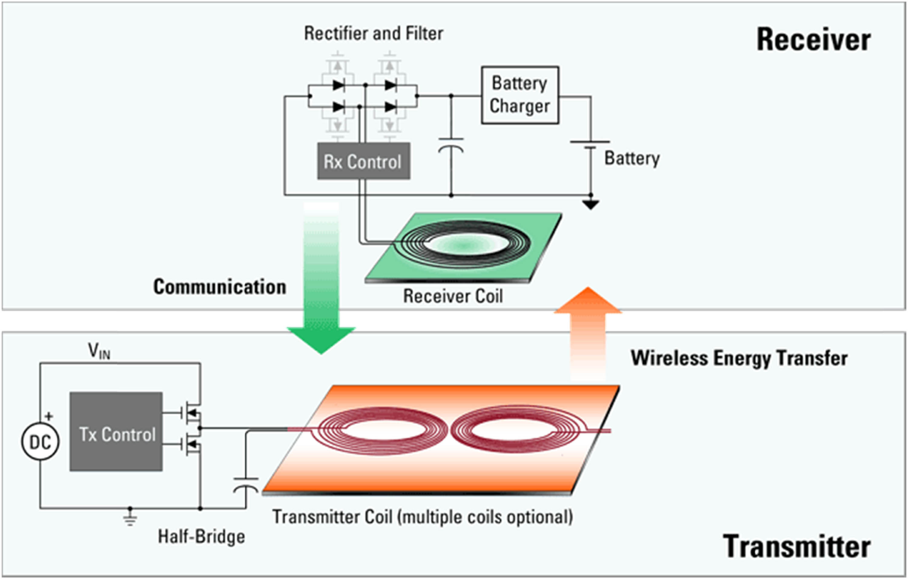
Magnetization as a function of applied field in charging system.
WCS converts the electric power into magnetic power by the TX coil and then captures it by the RX coil to charge the battery. However, if there is a metal object that appears between the TX coil and RX coil, the metal will be rapidly heated due to the magnetic field which may cause danger to the whole system. With the increase of the WCS power, the heat generated by the metal will also increase. Different metal materials would also cause the different temperatures to rise due to the different conductivity of electricity or magnetic permeability. Table 1 shows the temperature variation of different metals in a 1 kW@85 kHz WCS system. It can be seen that the temperature of IRON would increase to nearly 100 degrees in 10 s. Therefore, metal object detection technology is needed to strengthen the safety and reliability of WCS.
Variation in the WCS
| Material | Size (mm) | Thickness (mm) | Conductivity (S m−1) | Permeability (H m−1) | ∆T (deg) |
|---|---|---|---|---|---|
| Aluminum | 50 × 50 | 1.0 | 3.96 × 10⁷ | 1.0001 | 14 |
| Copper | 50 × 50 | 1.0 | 5.76 × 10⁷ | 0.9999 | 6 |
| Iron | 50 × 50 | 1.0 | 1.03 × 10⁷ | 5,000 | 160 |
| Iron | 25 × 25 | 1.0 | 1.03 × 10⁷ | 5,000 | 80 |
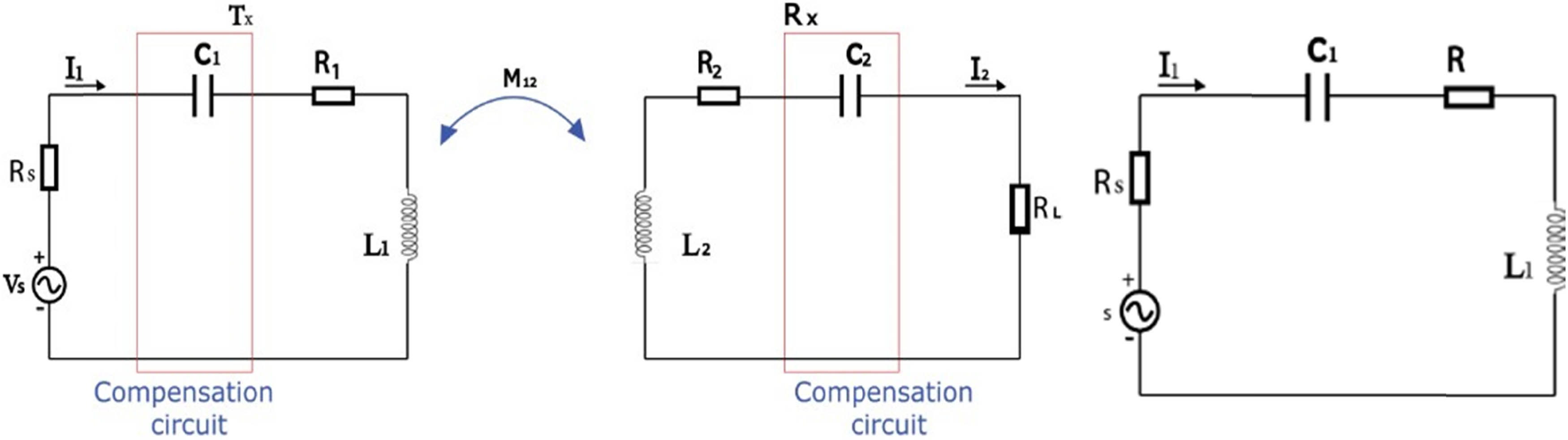
Foreign object detection method comprises the additional circuits within the WPT system for the target detection and computes the variation in the parameters through the validation of the existing objects. In those methods, detection theory is implemented with the metal object model with the equivalent circuit design. The foreign objects are computed in the WPT system induced with the coil for transmission. In between the transmitter pad, the ground and metal objects are placed on the surface with the pad for trans mission. The transmission distance between coils is evaluated based on the metal objects that impacts the coil for the transmission, and it does not have a significant effect on the receiver coil in the EVC system. It is observed that foreign objects affect the transmission coil with the neglected mutual inductance in the model and have effects on the reflected objects in the transmission coil with variation in internal resistance for the transmission coil. Figure 2 represents the internal resistance as well as the inductance circuit of the transmission coil and the foreign object detection in the electric charging system. Moreover, with the minimal inductance, minimal variation is observed for the transmission coil internal inductance. Also, the developed model assumed that mutual inductance does not lie between the transmission coils.

Working model prototype for WCS.
The electric charging system operating frequency is denoted as ω with the equivalent circuit expression presented in Eq. (1)
In the transmission coil, the impacts on the foreign object detection with the estimation of the equivalent circuit are presented in Eq. (2)
where,
Eq. (3) provides the effect of foreign object detection is examined the examination expressed that internal resistance increases and decreases the self-inductance in the coil for the transmission. The estimated system parameters tend to the metal object appearance with the detection of foreign objects with the impedance–deviation in the WPT system being presented in Eq. (3).
With the incorporation of the metal objects, the real and imaginary parts are computed for the impedance detection deviation. The proposed model uses the real impedance deviation for the transmission coil to validate the existence of foreign objects. WPT system comprises voltage and current sensors that are processed with the sensor.
3.1 Estimation of the voltage and current for the foreign object
With the emergence of foreign objects, input impedance is evaluated based on the variation in system voltage as well as current for identification of the MOD. The reflection occurred from the foreign objects performs the equivalent circuit receiver and transmitter operation as shown in Figure 3.
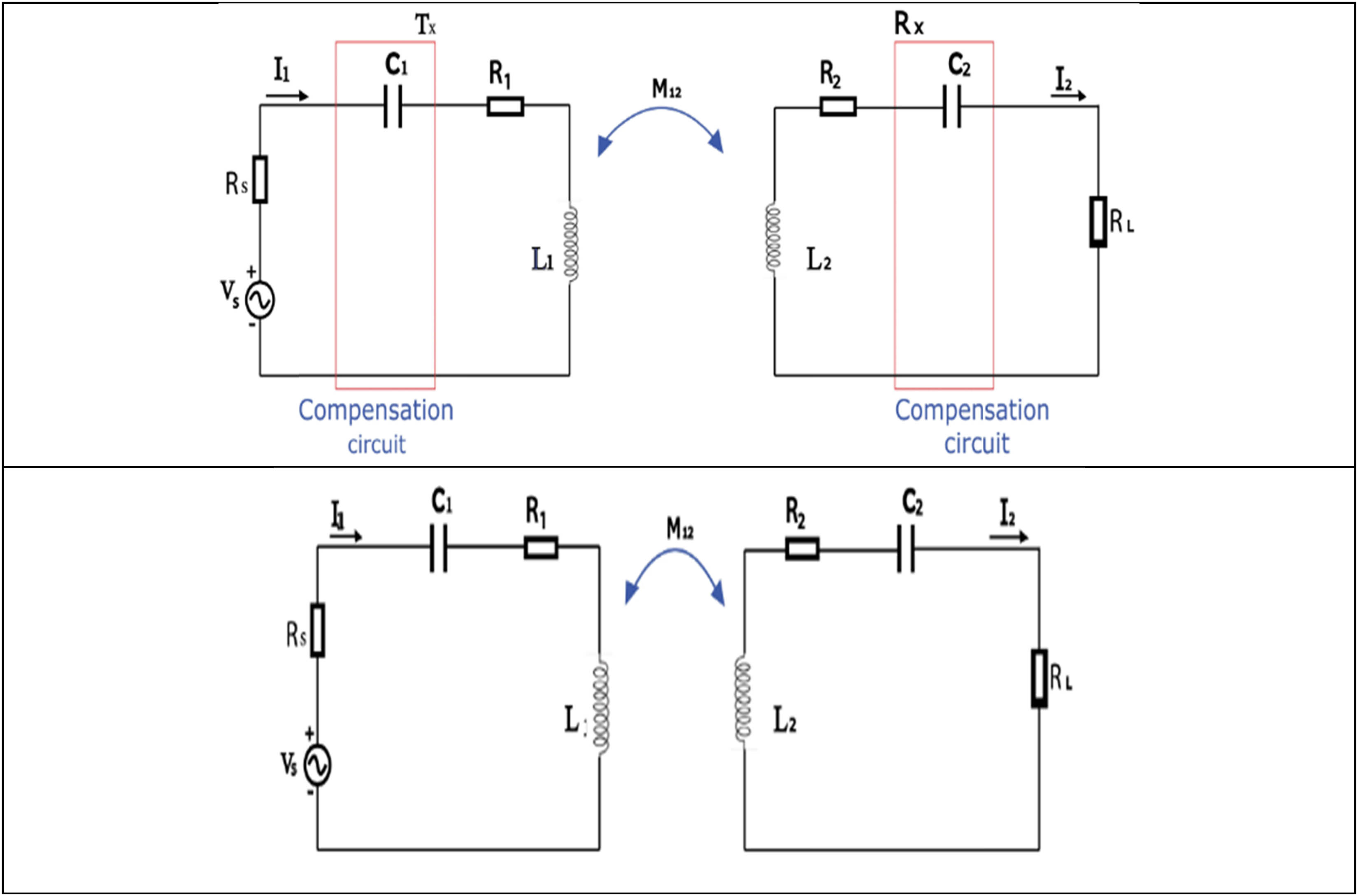
Foreign objects in the wireless charging system detection equivalent circuit.
Based on Eqs. (1)–(3), the simplified form of the circuit is presented in Eq. (4)
The coil current and voltage involved in the transmission are presented in Eqs. (5) and (6)
The foreign object in the battery-operated power charging impacts the voltage and current. Through application of the MOD method, the supply current is monitored and examined for the voltage estimation in the transmission coil. With the incorporation of the foreign objects, the voltage and current threshold values are computed and immediately shut down the fault mode in the charging system. Additionally, waveform-based switches are utilized for the variation in the metallic object inductive characteristics for the different responses in the foreign objects to drain the tuned receiver waveform. Through the power switches with the drain waveform, the metal objects are validated for their existence in the charging station.
3.2 Phase shift estimation with the foreign object detection
The phase voltage and current in the coil are computed as in Eq. (7)
The transmitter voltage as well as current is computed for foreign object detection with the shift in phase. Through phase shift detection, the proposed model tracks the coil in the transmission current and voltage with the appropriate phase shift. With the predetermined threshold value, the existence of the metal objects is computed, and the system categorizes the effective operating condition.
The resonant frequency of the charging point computed for the foreign object detection is presented in Eq. (8)
Through the consideration of the equivalent circuit, the charging point resonance voltage on both sides is presented as v c1 and v c2. The resonance capacitance value is denoted as C 2. L 2eq and R 2eq for the equivalent inductance and resistance in the receiver coil are as presented in Eq. (9)
In Eqs. (7)–(9), the resonant angular frequency is stated as ω r and Q, and the receiver coil factor is expressed as in Eqs. (10) and (11)
Based on Eq. (11), the effects of the foreign objects are evaluated with the internal equivalent circuit which leads to decreased inductance and increased resistance. This leads to the increased resonance frequency for the decreased Q factor, and detection parameters are estimated with the Q factor. With the use of a receiver coil, the Q factors are measured on both sides of resonance capacitance. The receiver side high-pass filter comprised of the LC circuit and Q-factor are estimated based on the computed peak value defined as in (v c2 − v c1)/v c1 as in Eq. (12) where,
The resonance frequency ω r computed based on the value of ω as in Eq. (13)
With the variation in power-source frequency, peak levels are estimated as the |v c2 − v c1|/|v c1| stated as the Q factor. Foreign objects in the electric charging system are computed based on the estimated Q values.
3.3 Design of integrated coil for foreign object detection
To prevent danger when a foreign object enters WCS during charging, a detection device is needed to find out whether a foreign object exists in WCS or not. However, the detection unit nowadays can only detect metal objects as well as living objects independently. Therefore, a detection coil which could be utilized to detect metal and living objects is presented in Figure 4.
Wireless charging circuit integrated with the equivalent circuit.
3.3.1 Foreign object detection strategy
Since the WCS could be used in various environments, the need for metal and living object detection is quite different. Therefore, a time division multiplexing detection process is introduced in this study as shown in Figure 5.
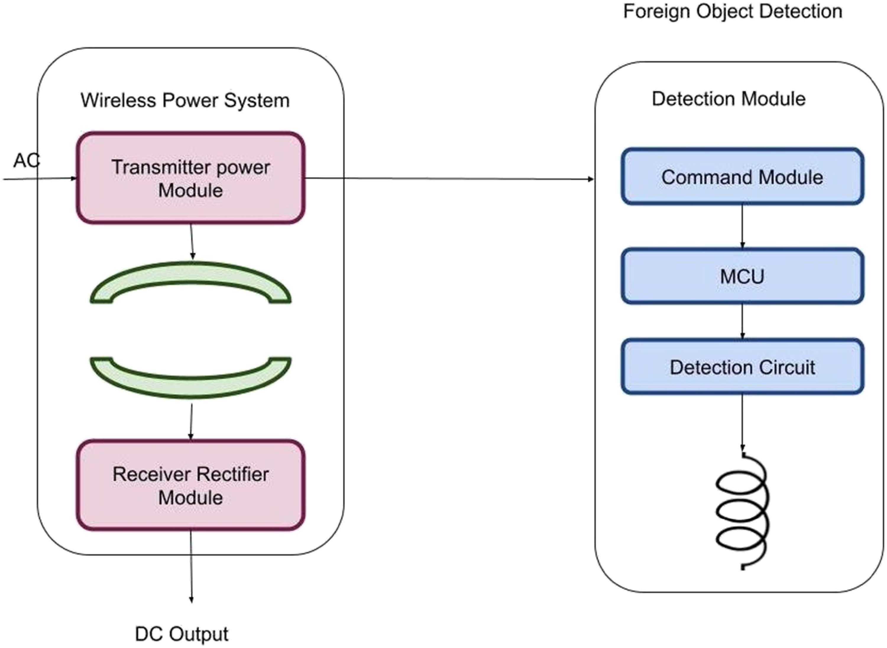
Structure of wireless charging system with coil.
At the beginning of the detection process, the execution proportion of foreign object detection could be defined according to user requirements (e.g., 70% of metal object detection and 30% of living object detection in one detection cycle). During the WCS operation, the detection process will switch to different object detection functions according to the preset proportion in turns. When the detection system switches to the metal object detection mode (short-circuit mode), the microcontroller will measure whether the coil voltage exceeds the preset value. When the system switches to the living object detection mode (open-circuit mode), the microcontroller will measure the equivalent capacitance of the coil and resonant frequency of the LC resonant circuit to determine whether equal capacitance and resonant frequency are outside the preset range. Once the coil voltage variation or the capacitance exceeds the preset value, a warning will be broadcasted by MCU and stop the WCS immediately.
4 Experiment and result analysis
The integration of the coils sometimes means that the power transfer efficiency would be lower because of the variation of the key parameters such as inductance. In this study, the inductance variation of the integrated coil was simulated by ANSYS/MAXWELL. The simulation result shows that the inductance value of the transmission coil is 143.43 µH and the integrated circuit is 141.57 µH, which shows the detection circuit has a very small influence on the system parameter. Table 2 presents the quantitative analysis of the phase shift for the charging system.
Quantitative analysis of phase shifter
| Parameter | RMSLE for 10-fold increase | OFV for 10-fold decrease | P* | CI | CV% |
|---|---|---|---|---|---|
| A1 | 0.216 | 206.569 | 1137 | [449, 1150] | 31.56 |
| A2 | 0.684 | 317.462 | 77.46 | [76.7, 82] | 2.96 |
| A3 | 0.247 | 210.571 | 6.892 | [4.92, 13.1] | 34.6 |
4.1 RMSLE (root mean squared logarithmic error)
RMSLE is a metric commonly used to evaluate the accuracy of predictive models, particularly in regression problems.
The values provided for each parameter represent the RMSLE scores associated with the phase shifter parameters.
4.2 OFV for 10-fold decrease (objective function value)
The OFV represents a measure of how well a mathematical model fits the observed data.
The values mentioned for each parameter indicate the OFV when it is de creased by a factor of 10 compared to a reference value.
4.3 P* (parameter estimate or value)
P* refers to the estimated value or estimate of a specific parameter.
The values provided represent the estimated values or calculated estimates for each parameter.
4.4 CI (confidence interval)
The confidence interval (CI) provides a range of values within which the true parameter value is expected to fall with a certain level of confidence.
4.5 CV% (coefficient of variation)
The coefficient of variation (CV%) is a measure of relative variability and represents the standard deviation as a percentage of the mean.
The values provided represent the coefficient of variation for each parameter.
The sensitivity of the foreign object location was also been simulated, and the results are shown in Figure 6. A metal plate of size 30 mm × 30 mm × 5 mm is used to place at eight different locations on the detection coil. Totally four different metals are used to test the detection function, and the detection results are shown in Figure 7. It shows that the coil could provide a magnetic field variation of over 5% which is able to be used in metal foreign object detection.
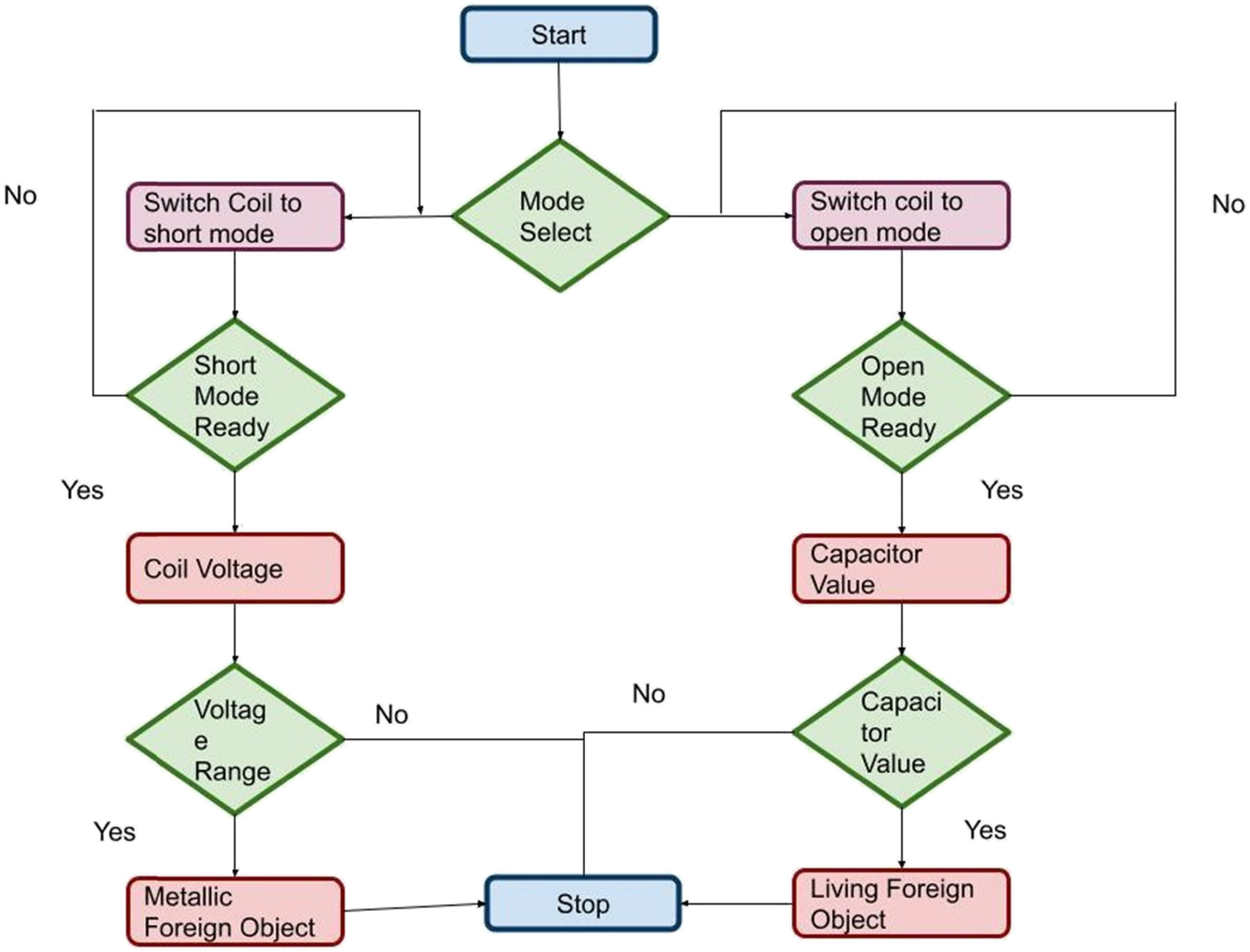
Flow chart of integrated coil for foreign object detection.
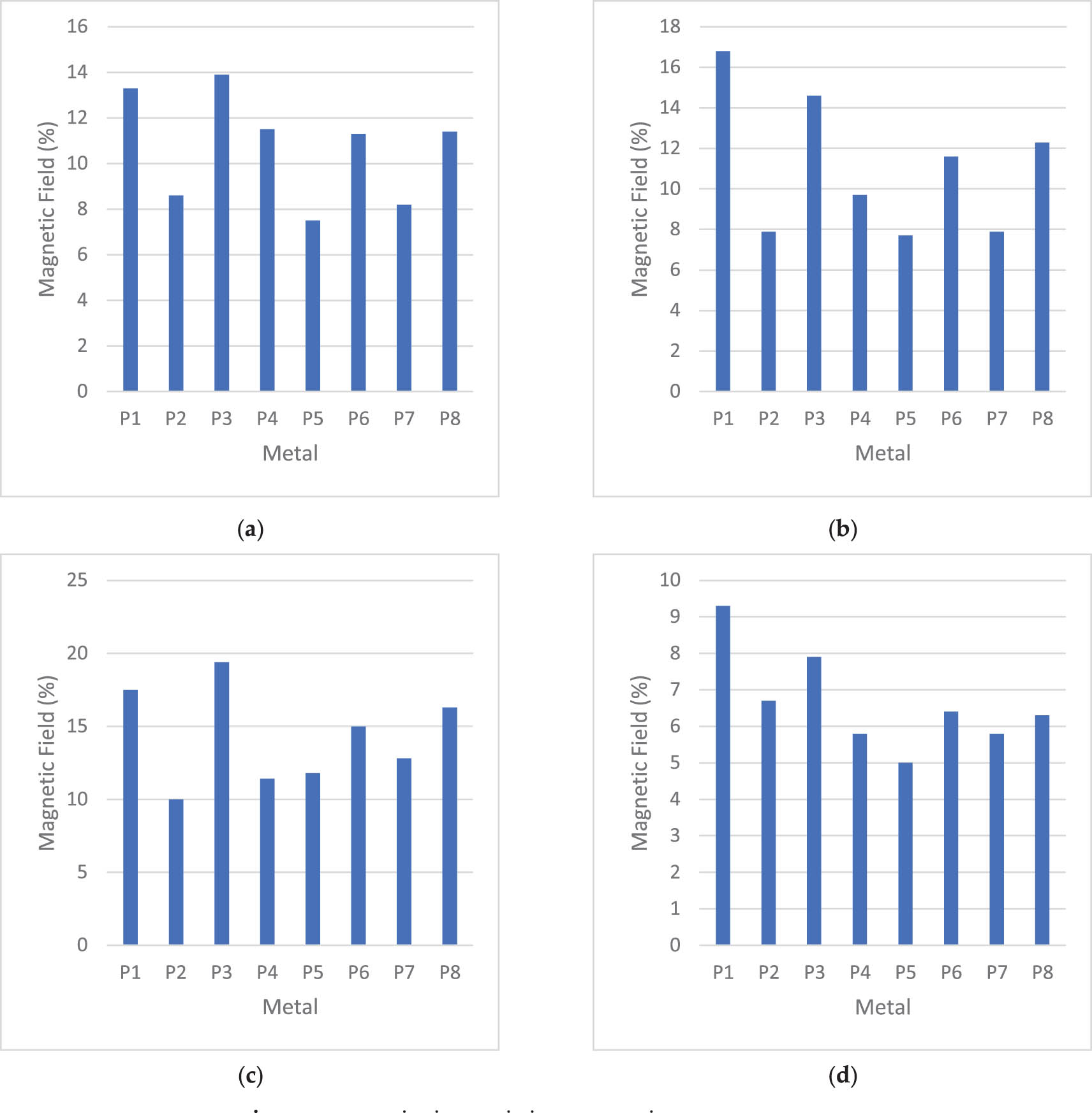
Magnetic field variation: (a) aluminum, (b) copper, (c) iron, and (d) steel.
In order to examine the detection coil function, a small-scale prototype system experiment is executed. A 25 W WCS with a working frequency of 85 kHz and a system efficiency of 85% are integrated with a 3n-type detection coil. The ANSYS graphics software is used to monitor the detection coil voltage variation and the equivalent capacitance (Figures 8 and 9).
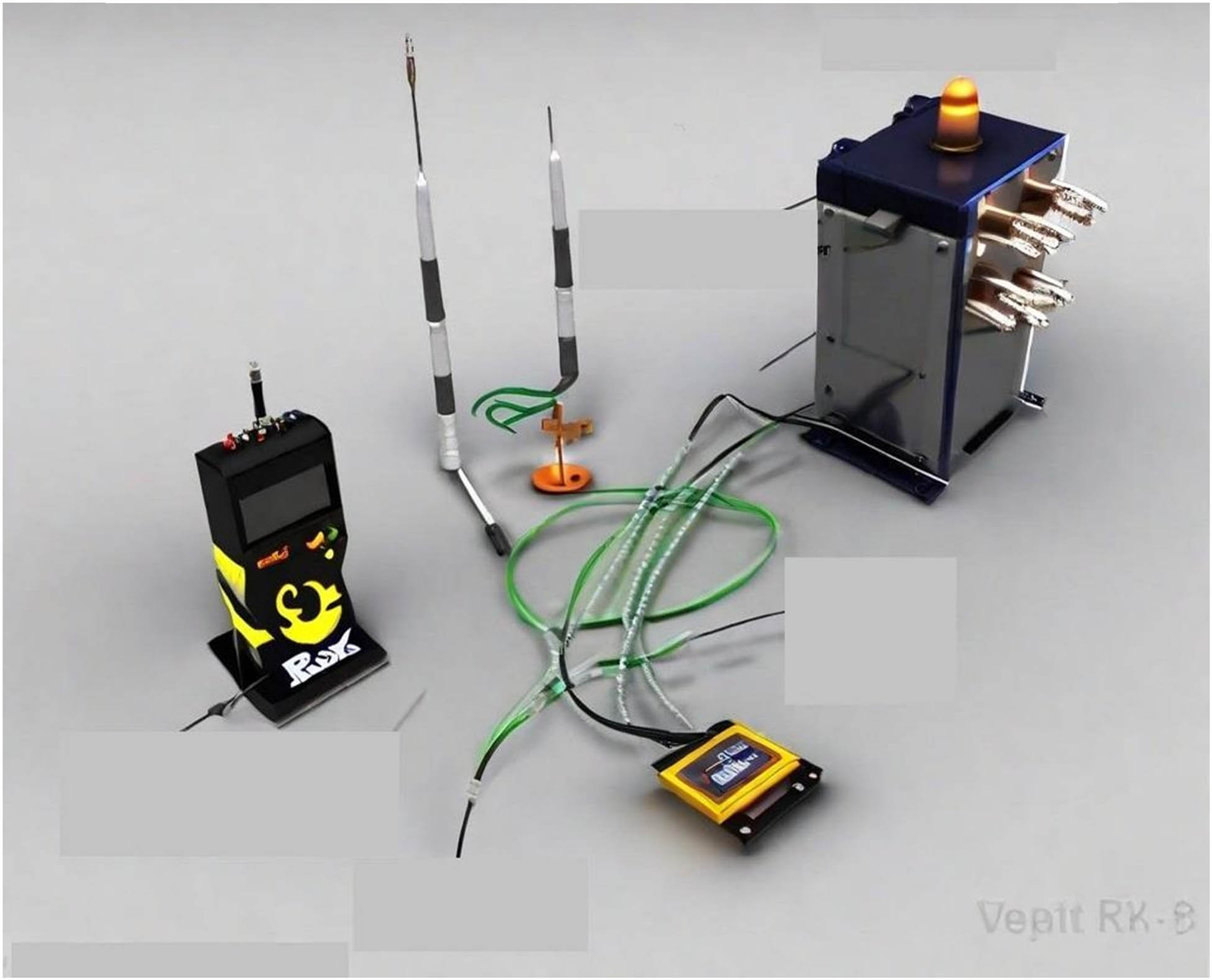
Parts used for detection coil function.
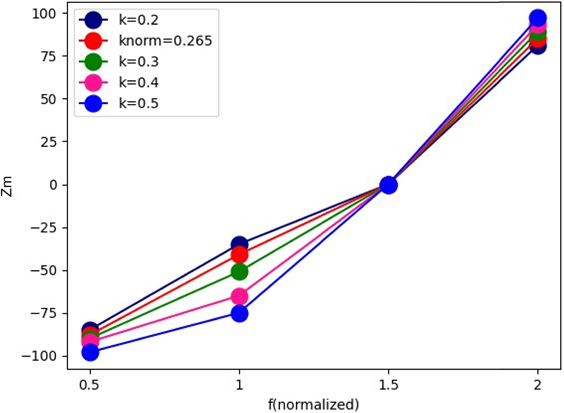
Metal detection rate for varying k.
The coupling coefficient between the transmitter and receiver coils has a direct impact on how effectively a wireless power transfer system operates. The degree of magnetic coupling between the two coils is represented by the coupling coefficient, which is frequently represented by the letter “k.” In wireless power transfer systems, the receiver coil experiences a voltage as a result of the magnetic field created by the transmitter coil. The amount of the magnetic field produced by the transmitter coil that actually interacts with and produces a voltage in the reception coil is quantified by the coupling coefficient. Power transfer is more effective when the coupling coefficient is larger since it denotes a stronger magnetic coupling between the coils. A smaller coupling coefficient, on the other hand, denotes weaker coupling, which results in more energy losses and less efficiency. The efficiency of the system for the varying coupling coefficient and the efficiency of the coil estimated for the different materials are evaluated. In Figure 10, the variation of the material with respect to the times is presented.
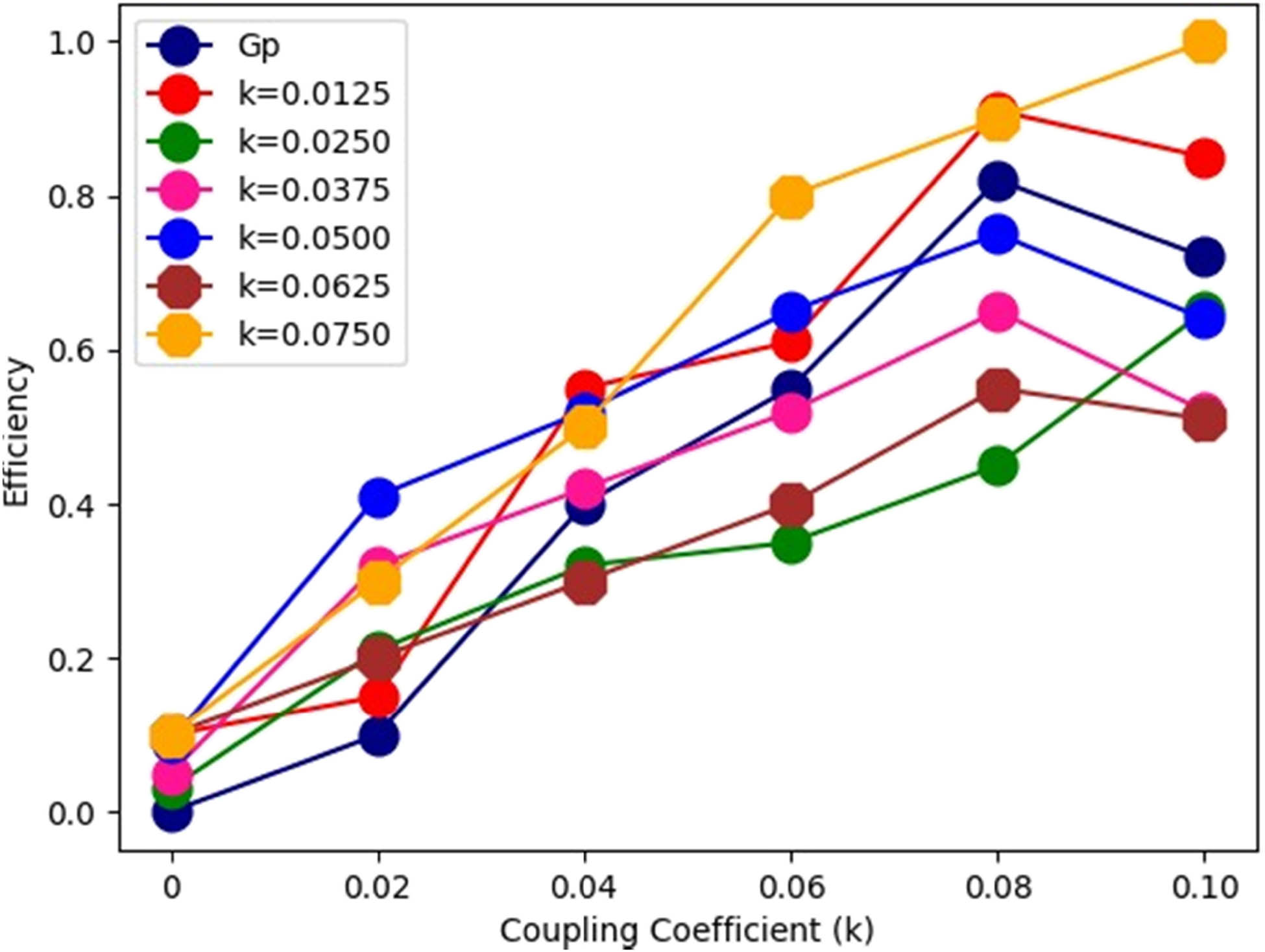
Efficiency for the coupling coefficient.
The variation of a coil based on time typically refers to the behavior or changes that occur in the coil’s electrical properties or magnetic fields over time. Several factors can cause variations in a coil, including the applied voltage or current, the frequency of the signal, the presence of external magnetic fields, and the characteristics of the materials used in the coil.
For metal foreign object detection, an iron can is placed between TX and RX coils as shown in Figure 11.
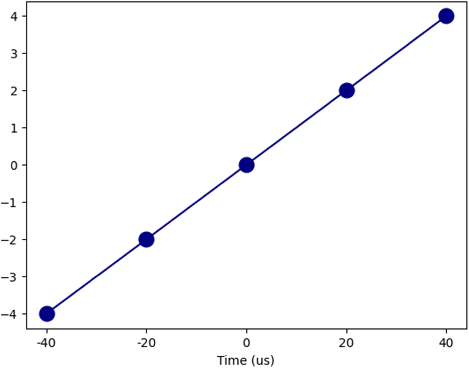
Variation of coil based on time.
A normalized voltage difference variation between the adjacent coils (from 920 to 1,000) immediately appears which successfully indicates the intrusion of a metal object. For living foreign object detection, the palm is used for testing (Figure 12). The palm is gradually extending into the gap between TX and RX coils. Figure 12 shows a significant variation of the bioequivalence capacitance which drops from 32,000k to 31,650k (nF), and the value changes by 1%. Since the bioequivalence capacitance has only 0.1% variation when there is no invasion of living objects, the 1% change of the capacitance can successfully be used to distinguish the existence of living objects (Figure 13).
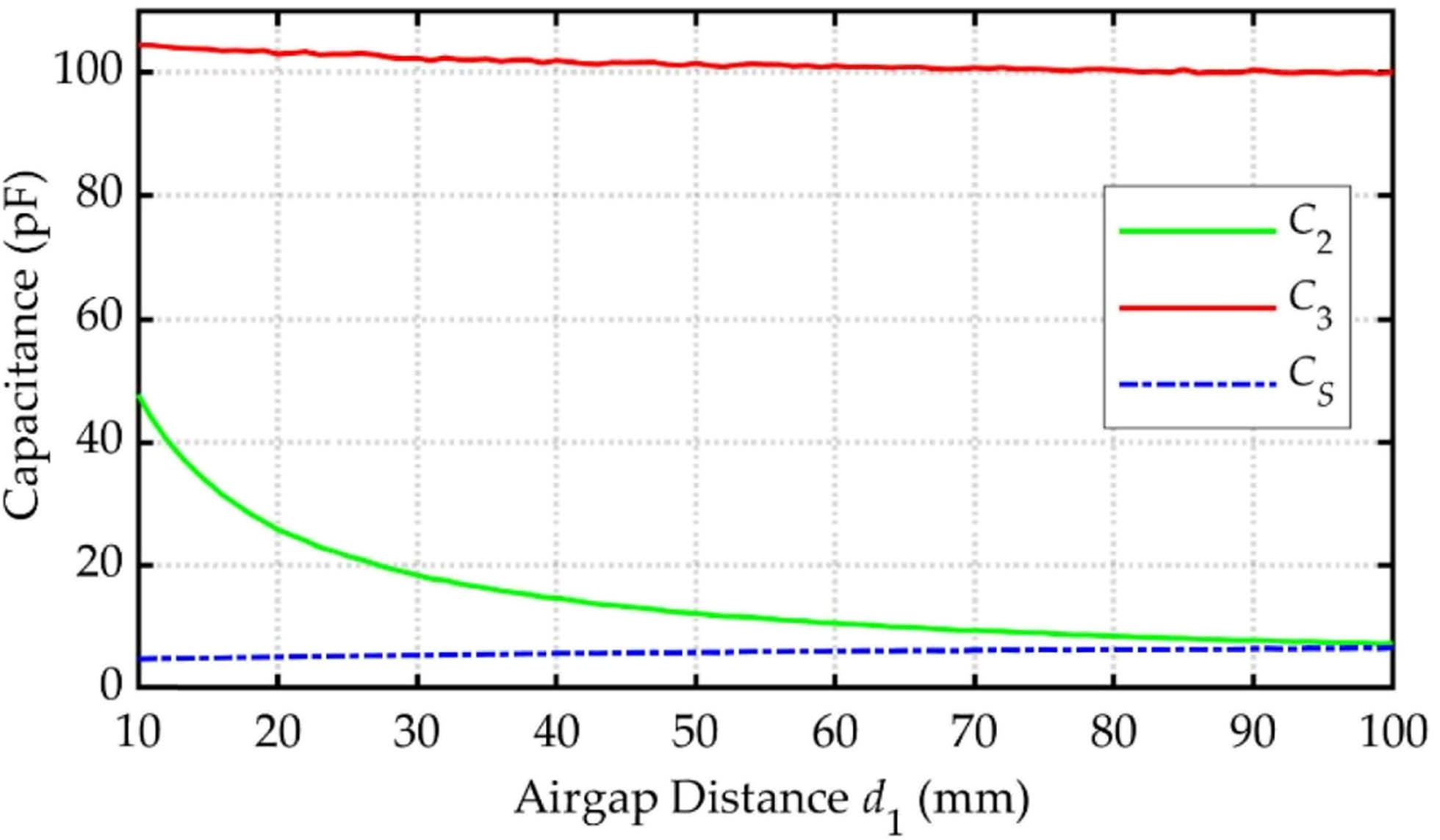
Capacitance for the metal object.
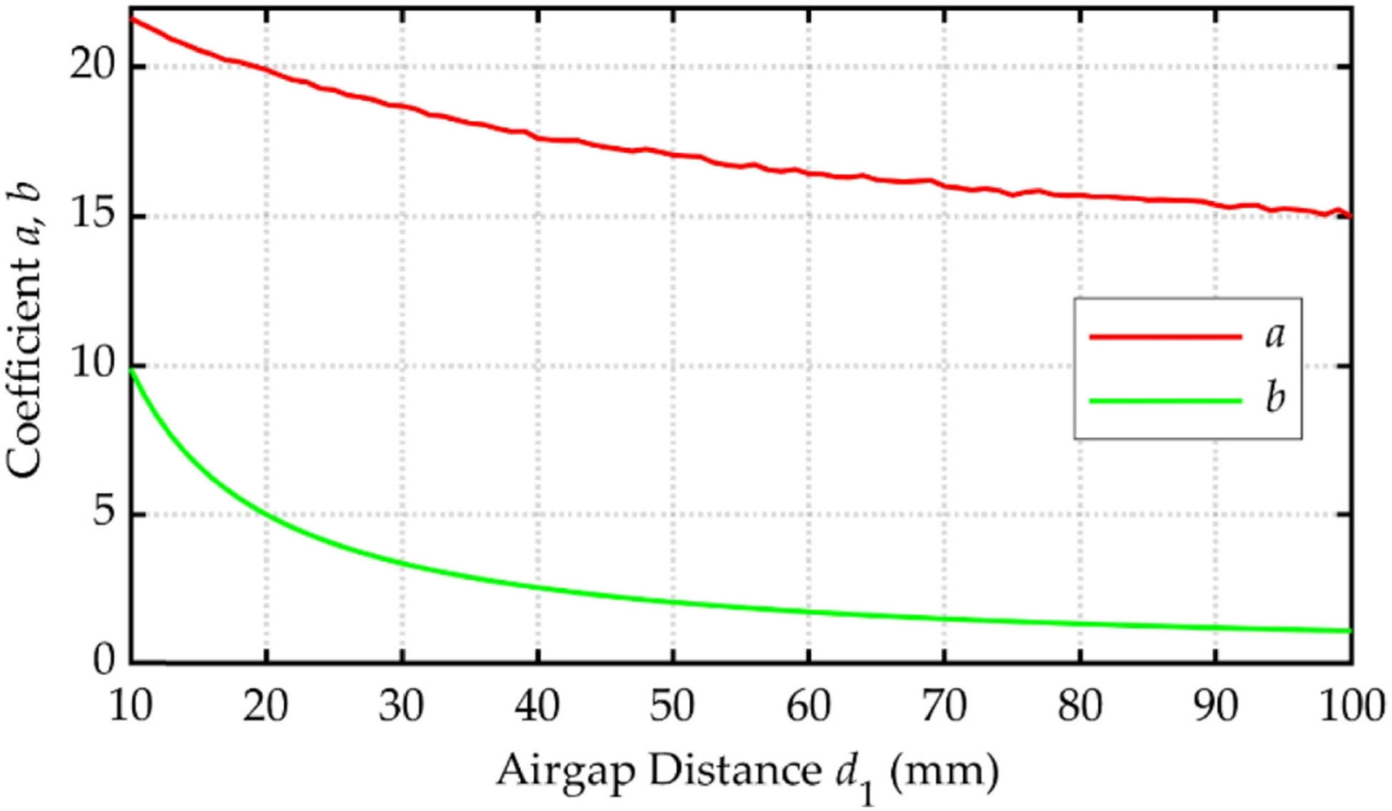
Capacitance for the living objects.
The varying capacitance of various object-based capacitors, when used for induction electric charge, is shown by the authors in Figures 11 and 12. When there is a certain gap between 10 and 100 mm, a different coefficient value will be obtained. This is because there is a loss in energy transfer at a particular distance in magnetic-field induction as the gap widens. Yet, after a given distance, the electric charge transfer may still be present without significantly changing, since very little energy is being received at the receiver end. The coefficients of c1 and c2 are undoubtedly changed by this, but the coefficient of c3 is unaffected since no curve is visible when the air gap is raised.
5 Conclusions
Wireless Power transfer technology has been adopted in the EVC system for FOD. Electric charging vehicle system with FOD needs to withstand the transmission and safety application based on the requirements. This article proposed an equivalent circuit model for foreign object detection for the incorporation of the coil in the circuit. The developed model exhibits a 5% variation for the material coil in the electric vehicle wireless charging system.
Acknowledgments
The authors extend their appreciation to the Deanship of Scientific Research at Imam Mohammad Ibn Saud Islamic University (IMSIU) for funding and supporting this work through Research Partnership Program No. RP-21-07-10.
-
Funding information: This work was supported by Imam Mohammad Ibn Saud Islamic University (IMSIU), Riyadh, Saudi Arabia, under grant number RP-21-07-10.
-
Author contributions: Conceptualization, all authors; methodology, R.R.C.; software, A.A.; validation, A.A.; formal analysis, all authors; writing – original draft preparation, A.A.; writing – review and editing, all authors. All authors have read and agreed to the published version of the manuscript.
-
Conflict of interest: The authors declare no conflict of interest.
References
[1] Meng T, Tan L, Zhong R, Xie H, Huang X. Research on metal foreign object detection of electric vehicle wireless charging system based on detection coil. World Electr Veh J. 2021;12:203.10.3390/wevj12040203Search in Google Scholar
[2] Tian Y, Guan W, Li G, Mehran K, Tian J, Xiang L. A review on foreign object detection for magnetic coupling-based electric vehicle wireless charging. Green Energy Intell Transp. 2022;1:100007.10.1016/j.geits.2022.100007Search in Google Scholar
[3] Lu J, Zhu G, Mi CC. Foreign object detection in wireless power transfer systems. IEEE Trans Ind Appl. 2021;58:1340–54.10.1109/TIA.2021.3057603Search in Google Scholar
[4] Wang J, Gao J, Yang A, Zhou J. Impedance Identification-Based Foreign Object Detection for Wireless Power Transfer System. 2022 IEEE 31st International Symposium on Industrial Electronics (ISIE); 2022 Jun 1–3; Anchorage (AK), USA. IEEE, 2022. p. 895–8.10.1109/ISIE51582.2022.9831611Search in Google Scholar
[5] Sun Y, Liu J, Liang C, Wei G, Zhu C, Song K. Design of high sensitivity foreign object detection system in wireless charging based on the variation of detection coils impedance. In: Chen Q, Yang Q, Wang L, Liu D, Han X, Meng G, editors. The Proceedings of the 9th Frontier Academic Forum of Electrical Engineering. Lecture Notes in Electrical Engineering vol. 743. Singapore: Springer; 2021. p. 775–89.10.1007/978-981-33-6609-1_71Search in Google Scholar
[6] Luo X, Liu Z, Zhai H, Hou Y, Feng G, Li X. Optimized design of the detection coils for the metal foreign object detection system applied to wireless power transfer. Energy Rep. 2022;8:883–90.10.1016/j.egyr.2022.02.031Search in Google Scholar
[7] Niu S, Zhang C, Shi Y, Niu S, Jian L. Foreign object detection considering misalignment effect for wireless EV charging system. ISA Trans. 2022;130:655–66.10.1016/j.isatra.2022.04.016Search in Google Scholar PubMed
[8] Son S, Lee S, Rhee J, Shin Y, Woo S, Huh S, et al. Foreign object detection of wireless power transfer system using sensor coil. 2021 IEEE Wireless Power Transfer Conference (WPTC); 2021 Jun 1–4; San Diego (CA), USA. IEEE, 2021. p. 1–4.10.1109/WPTC51349.2021.9458010Search in Google Scholar
[9] Shi W, Dong J, Soeiro TB, Bauer P. Integrated solution for electric vehicle and foreign object detection in the application of dynamic inductive power transfer. IEEE Trans Veh Technol. 2021;70:11365–77.10.1109/TVT.2021.3112278Search in Google Scholar
[10] Son S, Shin Y, Woo S, Ahn S. Sensor coil system for misalignment detection and information transfer in dynamic wireless power transfer of electric vehicle. J Electromagn Eng Sci. 2022;22(3):309–18; Du K, Zhu GR, Lu JH, Pang MY. Metal object detection method in wireless electric vehicle charging system. J ZheJiang Univ. 2022;56:56–62.Search in Google Scholar
[11] Tian Y, Li Z, Lin Y, Xiang L, Li X, Shao Y, et al. Metal object detection for electric vehicle inductive power transfer systems based on hyperspectral imaging. Measurement. 2021;168:108493.10.1016/j.measurement.2020.108493Search in Google Scholar
[12] Sato S, Nakamura S. Proposal of wireless charging which enables magnetic field suppression at foreign object location. Energies. 2022;15:1028.10.3390/en15031028Search in Google Scholar
[13] Li S, Li H, Wu Z, Bao G, Qian K, Li Y. Foreign object detection for LCC-S wireless power transfer system based on LSTM. 2021 IEEE International Conference on Emergency Science and Information Technology (ICESIT); 2021 Nov 22–24; Chongqing, China. IEEE, 2022. p. 165–9.10.1109/ICESIT53460.2021.9696918Search in Google Scholar
[14] Prosen N, Milanovič M, Domajnko J. On-line foreign object detection using double DD coils in an inductive wireless power transfer system. Sensors. 2022;22:1637.10.3390/s22041637Search in Google Scholar PubMed PubMed Central
[15] Kim S, Choi W, Lim Y. Metal object detection in a wireless high-power transfer system using phase–magnitude variation. Electronics. 2021;10:2952.10.3390/electronics10232952Search in Google Scholar
[16] Qi C, Duan H, Guo J, Sun T, Wang W, Yang F. A rack coil for metal foreign object detection in WPT system. IECON 2021–47th Annual Conference of the IEEE Industrial Electronics Society; 2021 Oct 13–16; Toronto, Canada. IEEE, 2021. p. 1–5.10.1109/IECON48115.2021.9589970Search in Google Scholar
[17] Adawy A, Bouattour G, Yuan Y, Ibbini M, Kanoun O. A Compact Receiving Side Circuit for Wireless Power Transfer with Foreign Object Detection Technique. In: Prasad RV, Pesch D, Ansari N, Benavente-Peces C, editors. Proceedings of the 11th International Conference on Sensor Networks; 2022 Feb 7–8; Vienna, Austria. SCITEPRESS, 2022. p. 263–271.10.5220/0011028000003118Search in Google Scholar
[18] Niu S, Niu S, Zhang C, Jian L. A super-sensitive metal object detection method for DD-coil-engaged wireless EV chargers by passive electromagnetic sensing. Energy Rep. 2022;8:370–9.10.1016/j.egyr.2022.08.122Search in Google Scholar
[19] Luo Y, Li Z, Wang S, Li Y. Electric vehicle wireless charging system transmission model based on two-port network. J Phys Conf Ser. 2022;2187:012069.10.1088/1742-6596/2187/1/012069Search in Google Scholar
[20] Wang J, Shao J, Ma X. Numerical Investigations of Electric Vehicle Wireless Charging Systems under the Interference of Metallic Foreign Objects. In: Liang X, Li Y, He J, Yang Q, editors. The proceedings of the 16th Annual Conference of China Electrotechnical Society. Lecture Notes in Electrical Engineering vol 890. Singapore: Springer; 2022. p. 964–77.10.1007/978-981-19-1870-4_101Search in Google Scholar
[21] Zhang W, Mo Q, Yan P, Liu Y. Simultaneous metal object detection and coil alignment for wireless EV chargers using planar coil array. IEEE Trans Instrum Meas. 2021;70:1–11.10.1109/TIM.2021.3126394Search in Google Scholar
[22] Li Y, Zhang Q, Liu X, Xiao N, Ning P, Li Y. Metal foreign body detection based on double/multiple differential coils pair magnetic module. J Magn Magn Mater. 2022;559:169542.10.1016/j.jmmm.2022.169542Search in Google Scholar
[23] Alshammari A, Chabaan RC. Sppn-Rn101: Spatial pyramid pooling network with resnet101-based foreign object debris detection in airports. Mathematics. 2023;11:841.10.3390/math11040841Search in Google Scholar
[24] Gong Y, Otomo Y, Igarashi H. Sensorless metal object detection for wireless power transfer using machine learning. COMPEL-Int J Comput Math Electr Electron Eng. 2021;41(3):807–23.10.1108/COMPEL-03-2021-0069Search in Google Scholar
[25] Vinko D, Bilandžija D, Filipović L. Drawbacks of Step Response Method for Detection of Foreign Metal Objects in Wireless Power Transfer System. 2022 45th Jubilee International Convention on Information, Communication and Electronic Technology (MIPRO); 2022 May 23–27; Opatija, Croatia. IEEE, 2022. p. 158–61.10.23919/MIPRO55190.2022.9803549Search in Google Scholar
[26] Xia J, Yuan X, Li J, Lu S, Cui X, Li S, et al. Foreign object detection for electric vehicle wireless charging. Electronics. 2020;9:805.10.3390/electronics9050805Search in Google Scholar
[27] Lin Y, Xiang L, Tian J, Tian Y. Metal object detection in a wireless power transfer system based on double-layer symmetric sensing coils. E3S Web Conf. 2020;185:01035.10.1051/e3sconf/202018501035Search in Google Scholar
[28] Niu S, Niu S, Zhang C, Jian L. Blind-Zone-Free Metal Object Detection for Wireless E.V. Chargers Employing D.D. Coils by Passive Electromagnetic Sensing. IEEE Trans Ind Electron. 2023;70(1):965–74.10.1109/TIE.2022.3150114Search in Google Scholar
[29] Jeong SY, Kwak HG, Jang GC, Choi SY, Rim CT. Dual-purpose nonoverlapping coil sets as metal object and vehicle position detections for wireless stationary E.V. chargers. IEEE Trans Power Electron. 2018;33(9):7387–97.10.1109/TPEL.2017.2765521Search in Google Scholar
[30] Tian Y, Lin Y, Tian J, Xiang L. Multi-thread sensing coil design for metal object detection of wireless power transfer systems. Measurement. 2021;184:109952.10.1016/j.measurement.2021.109952Search in Google Scholar
© 2023 the author(s), published by De Gruyter
This work is licensed under the Creative Commons Attribution 4.0 International License.