Applied Thermal Engineering 31 (2011) 656e667
Contents lists available at ScienceDirect
Applied Thermal Engineering
journal homepage: www.elsevier.com/locate/apthermeng
Prediction and evolution of drop-size distribution for a new ultrasonic atomizer
Moussa Tembely a, *, Christian Lecot b, Arthur Soucemarianadin a
a
b
University of Grenoble, Laboratory of Geophysical and Industrial Fluid Flows, UMR 5519, BP 53, 38041 Grenoble, France
University of Savoie, Laboratory of Applied Mathematics, UMR 5127 CNRS, 73376 Le Bourget-du-Lac, France
a r t i c l e i n f o
a b s t r a c t
Article history:
Received 14 December 2009
Accepted 28 September 2010
Available online 7 October 2010
Complete modeling of a new ultrasonic atomizer, the Spray On Demand (SOD) printhead, was carried out
to enable its optimization. The modeling was focused on various factors, including nozzle vibrations and
a theoretical prediction of the SOD drop-size distribution. Assuming that the spray is generated based on
Faraday instability, a prediction of the drop-size distribution within the framework of a specific and
general Maximum Entropy Formalism (MEF) was developed. This prediction was formulated using the
conservation laws of energy and mass, as well as the three-parameter generalized Gamma distribution.
After establishing an analytical expression to estimate the Sauter Mean Diameter, a qualitative validation
of the model was performed by comparing predictions with experimental measurements of the dropsize distribution. The dynamic model is shown to be sensitive to operating conditions and physical
properties of the fluid. The prediction capabilities of the model were found to be adequate, paving the
way for optimization of the atomizer. The evolution of the drop-size distribution, under the coalescence
effect, was also assessed using a convergent Monte Carlo method to solve the distribution equation. This
was formulated in a mass flow algorithm, leading to a more physically relevant distribution.
� 2010 Elsevier Ltd. All rights reserved.
Keywords:
Nozzle conveying fluid
Spray
Maximum entropy formalism
Monte Carlo method
Coalescence
1. Introduction
It is well known that piezoelectric jet printing technology is
capable of depositing controlled amounts of fluid onto a specified
location very accurately. Combining this ability with an increasingly
wide selection of fluids has made the piezoelectric on-demand
jetting system a promising device for the development of innovative
industrial applications. Jet printing technology offers an amazingly
broad utilization range across a wide variety of applications, such as
biotechnology, electronics, pharmacology, micro-optics, and many
others that are only limited by our imagination [1]. Four major fluid
jetting techniques are commonly used: Drop On Demand (DOD),
Continuous Ink Jet (CIJ), Electro-Valve and Spray Technologies. The
work presented here focuses on an innovative spray technology that
may be qualified as a Spray On Demand (SOD) technology, where
spray is generated only when required. This constitutes a major
difference with classical spraying technologies, in which the jetting
is continuous. Inkjet printheads are advantageous because they are
non-contacting, minimizing the potential for contamination.
In general, classical printheads are well adapted to applications
that deal with Newtonian fluids. However, a growing number of
* Corresponding author. Tel.: þ33 456 521 120; fax: þ33 475 561 620.
E-mail address: moussa.tembely@ujf-grenoble.fr (M. Tembely).
1359-4311/$ e see front matter � 2010 Elsevier Ltd. All rights reserved.
doi:10.1016/j.applthermaleng.2010.09.027
engineering applications need robust devices that allow for the
ejection of rheologically complex fluids (e.g., polymers and fluids
with particles). In this paper, we present the underlying theory for
the optimization of an innovative Spray On Demand printhead (SOD)
that is under development. This printhead has the advantage of
being robust and relatively simple, enabling high-throughput
printing. In contrast to other printing techniques like CIJ or DOD, this
new device is able to eject fluids that are much more viscous or that
contain particles, for example, while lowering the risk of clogging. As
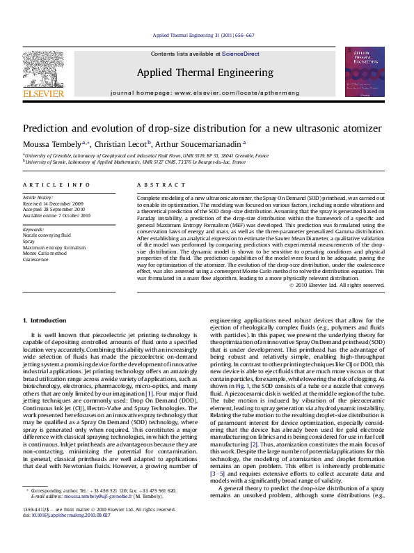
shown in Fig. 1, the SOD consists of a tube or a nozzle that conveys
fluid. A piezoceramic disk is welded at the middle region of the tube.
The tube motion is induced by vibration of the piezoceramic
element, leading to spray generation via a hydrodynamic instability.
Relating the tube motion to the resulting droplet-size distribution is
of paramount interest for device optimization, especially considering that the device has already been used for gold electrode
manufacturing on fabrics and is being considered for use in fuel cell
manufacturing [2]. Thus, atomization constitutes the main focus of
this work. Despite the large number of potential applications for this
technology, the modeling of atomization and droplet formation
remains an open problem. This effort is inherently problematic
[3e5] and requires extensive efforts to collect accurate data and
models with a significantly broad range of validity.
A general theory to predict the drop-size distribution of a spray
remains an unsolved problem, although some distributions (e.g.,
�M. Tembely et al. / Applied Thermal Engineering 31 (2011) 656e667
657
Fig. 1. Spray On Demand printhead and visualization of the spray.
Weibull and Rosin-Rammler distributions) follow from the physically-grounded percolation model of chaotic atomization [6]. In the
end, the application of these theories ultimately leads to curve fitting.
The generated droplets result from the dynamics of ligaments and
their fragmentation [7]. An analysis of ligament fragmentation based
on the assumption that it consists of sub-drops in different sub-layers
has been performed [8]. In this case, the ligament breakup was well
represented by gamma distributions. All of these models ultimately
lead to distributions that still must be fit with experimental data and
do not account for the effect of the atomizer. The significant number
of drops that constitute a spray does not allow for the precise
determination of the diameter or velocity of each drop. There is large
body of literature that discusses the prediction of a representative
drop diameter in a spray. However, there are relatively few publications dealing with the prediction of drop-size distributions. One
possibility to quantitatively describe a spray is to adopt the tools of
statistical analysis. Following a previous report [9], there are three
methods for modeling the drop-size distribution: Empirical Method,
Probability Function Method and Maximum Entropy Formalism
(MEF), which is the one adopted in the present work.
Despite its large presence in industrial applications, spray
modeling remains a challenge for computational methods and
experimental measurements when one wants to predict the dropsize distribution. Droplet generation is an extremely complex process
that cannot be precisely determined. Current approaches are either
semi-empirical or need to be adjusted to each operating condition
encountered. Based on ultrasonic atomization through the Faraday
instability of the SOD, we propose a drop-size distribution that is
based on physical evidence and is sensitive to operating conditions.
This type of approach is necessary to obtain a specific drop-size
distribution, which may be required in some applications. Extending
the MEF drop-size distribution to enable the generation of a temporal
evolution was also investigated. This could also be of great interest for
initializing sophisticated CFD spray modeling codes. In traditional
MEF approaches, the precise drop-size distribution is usually timeindependent. Here we propose a modeling of the time-dependent
drop-size distribution of the MEF. First, the distribution evolution
equation is derived and the Mass Flow Algorithm (MFA) is utilized to
simulate the equation with a convergent Monte Carlo method.
2. Spray generation with a vibrating nozzle
The SOD nozzle that conveys fluid is excited to an ultrasonic
mode at a frequency of fp ¼ 192 kHz using a piezoceramic actuator.
Subsequently, the pendent drop or film at the beveled nozzle tip
breaks up into droplets via a Faraday instability, establishing that
the frequency of the stationary surface wave corresponds to half of
the imposed working frequency (e.g., by the SOD nozzle) [10].
Based on experimental investigations [11,12], the mean droplet
diameter (D30) is proportional to the surface wavelength (l) for
ultrasonic spray generators, favoring capillary wave theory [13].
The crests of these surface waves breakup to generate droplets. The
droplet volume can be seen as a fraction of the crest volume
generated by the intersection of unstable standing waves. Equating
the mean droplet volume with a fraction of the crest volume leads
to the following relation:
2
D330 fl A
(1)
where A is the amplitude of the film at which an instability leads to
droplet ejection.
Using the fact that near the breakup point D30 fl, the following
relation can be deduced from (1):
(2)
Afl
To predict the droplet size generated from the surface wave, nonlinear dynamics analyses of the wave dispersion and interactions
should be performed. The few non-linear analyses available [14]
show that a square wave structure is formed preferentially for
small viscous liquids at frequencies >100 Hz. For this purpose, an
empirical relationship has been established in [15] for the unstable
wavelength that relates all of the main parameters, including the
fluid viscosity mf, for ultrasonic atomization (100 kHz) of a pistonlike inducement of the Faraday wave. This relationship can be
expressed as follows:
0
11=5
mf sf A
r2f fp3
lz@
(3)
where rf and sf are the density and the surface tension of the fluid,
respectively.
A quick analysis of Eq. (3) can be carried out by turning it into
a dimensionless form and by assuming that the unstable wavelength is expressed as l ¼ Pðs; m; fp ; rÞ. Taking the wavelength as
a characteristic length (we could also choose the wave amplitude A
instead knowing Afl), the velocity vc ¼ lfp and the previous
relationship given in Eq. (3) is simply equivalent to Re:We ¼ Const,
where Re ¼ rf vc l=mf and We ¼ rf v2c l=sf . Thus, this analysis relates
the unstable wavelength to all of the main forces involved: inertia,
viscosity and the surface tension effect. We prefer this relation to
the one given by Lang [11], which does not account for the viscosity.
3. New physically based MEF
Following [7], three interpretations have been attributed to the
fragmentation process: (i) a sequential cascade of breakups, which
is an interpretation that originated from Kolmogorov and leads to
the log-normal distribution; (ii) the aggregation scenario, which
makes use of the Smoluchowski kinetic aggregation process and
leads to the fact that the drop-size distribution displays an
�658
M. Tembely et al. / Applied Thermal Engineering 31 (2011) 656e667
exponential tail; and (iii) the Maximum Entropy Formalism (MEF),
which leads to a Poisson distribution, as presented by the author. It
is worth adding to these interpretations the idea of the dynamics of
ligaments, which assumes that they are constructed of blobs of
different layers [8].
Instead of being opposed, we show that these different interpretations could be complementary to some extent. From two
visions of the MEF, we derive a new formulation for predicting
drop-size distribution. This work shows that the MEF could lead to
the same result given by ligament dynamics, which are at the core
of spray formation. The droplets coming from the breakup of these
different ligaments can explain the polydispersity of the spray, even
though ultrasonic sprays are less disperse compared to other
techniques [16].
To establish a physically based approach, we propose a coupling
of what we distinguish as two complementary formulations using
MEF, which we designate as specific and general formulations. A
specific formulation is based on conservation laws; this formulation is proven to give satisfactory results on the spray, with
a drawback existing for small-size drops. Its advantage is that it
takes into account the device operating parameters. Thus, we
propose to couple this approach with a general formulation,
leading to the three-parameter generalized gamma distribution.
Indeed, this distribution takes into account the general characteristics of a spray, but does not take into account the unique features
of the atomization device.
the spray. In [17], a distribution is derived based only on the constraint
of mass conservation, and the deduced volume-based distribution
gives good results for a pressure swirl atomizer. The authors applied
the MEF not on the number-based fraction, but on the volume-based
fraction (which is not a probability, as explained in [18]). They end the
method by performing a variable change to deduce the number-based
drop-size distribution. Other attempts have been made by exploiting
this variable change to end up with an acceptable number-based
distribution. In fact, the challenge of this specific formulation is to
correctly predict the number-based distribution especially for small
droplet populations, which are mainly over predicted. To prevent this
over-prediction, the “variable change” has been carried out, but it
violates the MEF principle [18]. Since the introduction of the general
approach [19], the previous formulation has somehow been abandoned. The approach presented here revisits the abandoned specific
formulation and shows its complementarity with the general
formulation approach, as well as its consistency with the MEF principle. In fact, it is unclear how one can claim to predict a process that is
as complicated as the atomization without using as much information
as possible, including the useful information given by the specific
formulation. Many aspects have an influence on the generation
mechanism of the droplets, the atomizer itself and the fluid. In
addition to these constraints, a practical approach for spray modeling
is to use the minimum number of parameters to enable effective
computation. Our approach aims to meet these requirements by
coupling the presented specific formulation and the following general
formulation.
3.1. Specific formulation
3.2. General formulation
This formulation, which is sensitive to SOD operating conditions
and based on spray conservation laws, consists of maximizing the
following Shannon entropy:
S ¼
Z
(4)
hn ðDÞlnhn ðDÞdD
D
where hn(D) is the number-based drop-size distribution of the
spray. The integration is performed on all of the permissible states
R Dmax/N
R
, where Dmin, Dmax are the spray drop
of the diameter h Dmin/0
D
minimum and maximum diameters, respectively.
The associated constraints to Eq. (4) are as follows:
Normalization constraint
Z
hn ðDÞdD ¼ 1
(5)
D
Conservation law constraints
Z
hn ðDÞmk ðDÞdD ¼ Hk ; k ¼ 1.M
(6)
As previously mentioned, all atomization processes can be seen
as a breakup of a ligament. Therefore, ligament dynamics can be
seen as a general characteristic of a spray. Because of the random
liquid motions present in a ligament, the sub-drops of a layer overlap
and merge. The solution of that evolution equation [8] leads to the
following gamma function or gamma number-based distribution:
FLn ðx ¼ D=d0 Þ ¼
bb b 1
x
exp½ bx
GðbÞ
(8)
where d0 is the average blob or ligament diameter; and b is the
gamma distribution parameter.
Consider that the ligament population at the SOD nozzle is
distributed as follows:
FL ðd0 Þzdðd0
(9)
dl Þ
Unlike the case for the high speed jet ligament, the ligament
from the Faraday wave is less disperse, and assumed to have nearly
the same dimension, noted here as dl.
Therefore, we can deduce the drop-size distribution of the spray
(FSn(D)) using convolution of FLn(D/d0) and FL(d0) as follows:
D
where mk (D) is a function describing the state of the droplets (e.g.,
volume or energy); and Hk is the available information and known
moments of the distribution.
The solution of the system given in Eqs. (4)e(6) can be
expressed in the continuous form:
c
hn ðDÞ ¼ exp l0
X
k
c
!
lck mk ðDÞ
FSn ðDÞ ¼
where lk are the Lagrange multipliers in continuous form.
Until recently, this formulation of the MEF was applied using the
conservation laws of mass, momentum or energy. Its predictive
capability was quite satisfactory for the volume-based distribution of
dðd0 Þ
1
FL ðd0 ÞFLn ðD=d0 Þ
¼ FLn ðD=dl Þ
dl
dl
(10)
We can finally deduce the following:
b
FSn ðDÞ ¼
(7)
Z
1 b
b
ðD=dl Þ
dl GðbÞ
1
exp½
bðD=dl Þ
(11)
This gamma distribution could therefore represent the general
description of a spray (e.g., that of the SOD spray).
Adoption of the MEF formalism can also produce an alternative
description of a spray that leads to the gamma function. This
distribution is formulated with a single constraint on the diameter
expressing the definition of a mean drop diameter [19]:
�659
M. Tembely et al. / Applied Thermal Engineering 31 (2011) 656e667
Z
Dq Fn ðDÞdD ¼ Dqq0
(12)
D
where and q and Dq0 are two parameters of the distribution function, Fn(D).
To model the small drop limitation caused by the presence of
surface tension forces, a diameter-class probability distribution, g(D),
that continuously increases with the diameter is introduced [20]:
1
gðDÞ ¼ 2Da
where 2 is a constant and a is the third parameter of Fn(D).
This yields the three-parameter generalized distribution [20,21]:
"
� �a a 1
a qD
q
Fn ðDÞ ¼ � �
exp
a
G a q Dq0
q
a
D
q Dq0
!q #
Z
Fn ðDÞln
Fn ðDÞ
dD
mðDÞ
(14)
(15)
D
where mðDÞ ¼ gðDÞa 1 , which is the probability of reaching
a diameter D.
The specific approach enables determination of some parameters of the general formulation, as follows:
Dq0 ¼
8
<Z
:
Hk ¼
Z
D
91=q
=
Dq hn ðDÞdD
;
mk ðDÞFn ðDÞdD; k ¼ 1.M
We can express Ms differently in the following manner:
Ms ¼ rf Vspray ¼
This is carried out by maximizing the following relative entropy:
SR ¼
Fig. 2. Drop hanging at the nozzle tip and atomization modeling.
(13)
(16)
(17)
D
The constraints should be chosen to determine the three
parameters (Dq0,a,q) of the generalized gamma function, in addition to Eq. (16). These constraints should be as relevant as possible
and should reflect the physics of atomization. Note that the specific
formulation that we introduced was solely able to predict the dropsize distribution, although it poorly models the distribution for
small drops [9,18].
4. Application to the SOD spray
Predicting the drop-size distribution of the new Spray On
Demand (SOD) printhead is an important issue for device optimization and operation. These steps are required to further extend
device operation. In the following section, we apply the previous
approach to the SOD with the details of the specific formulation
constraints on mass and energy conservation.
4.1. Mass conservation
Let Ms be the mass of fluid accumulated at the nozzle tip. This
mass is ejected after an excitation time or operation of the SOD and
will breakup into droplets. It corresponds to the total mass of fluid
bursting at the nozzle tip interface due to Faraday instabilities,
which is a direct consequence of the acceleration. The mass Ms of
the fluid is a reference quantity on which we will make our argument of mass and energy conservation. Therefore, its precise value
is not significant. We assume Ms to be atomized into spray droplets
with the drop diameter space divided into nc classes of constant
width DD.
nc
X
mi ¼
i¼1
nc
X
rf Vi ¼ rf
i¼1
nc
X
(18)
rf Vi
i¼1
nc
pX
nc
p X
p
Ni D3i ¼ rf N
p D3 ¼ rf ND330
6 i¼1
6 i¼1 i i
6
(19)
where pi is defined as pi ¼ Ni/N and D30 is the volume mean
diameter. From Eq. (19), we can deduce the constraint upon mass
conservation as follows:
nc
X
pi d3i ¼ 1 with di ¼
i¼1
Di
D30
(20)
Before starting with the second constraint, the parameter Ms can
be expressed in terms of operating conditions and fluid properties.
For this purpose, a global analysis is carried out to determine Ms. As
suggested by experimental observation, atomization takes place
preferentially in the second half of the nozzle tip exit region (Fig. 1).
The surface tension is defined as the force per unit length acting
tangentially to the liquid-gas surface. By applying Newton’s second
law to a drop hanging at the tip, including a balance between
surface tension and gravity, we can deduce the following when
projecting on a vertical component (Fig. 2):
Ms gzFsf cosðp=2
ðqE
ab ÞÞ ¼ sf CsinðqE
ab Þ
(21)
where the force Fsf ¼ sf C, C is the boundary of the hanging drop.
The value of Ms corresponds to the fluid mass (drop) outside the
nozzle, which breaks up into spray; and ab represents the beveled
angle of the nozzle tip.
In Eq. (21), qE is the equilibrium contact angle between the liquid
fluid and the nozzle structure. This value is set based on the back
pressure so that qE > ab. The parameter Ph is the circumference of
the elliptical nozzle exit shape and is expressed as follows:
Ph ¼ 4aEðeÞ
(22)
The circumference of an ellipse is Ph ¼ 4aE(e), where the function E(e), with e being the eccentricity, is the complete elliptic
integral of the second kind. A good approximation from Ramanujan
is as follows:
�
Ph zp 3ða þ bÞ
qffiffiffiffiffiffiffiffiffiffiffiffiffiffiffiffiffiffiffiffiffiffiffiffiffiffiffiffiffiffiffiffiffiffiffi�
ð3a þ bÞða þ 3bÞ
(23)
where a is the semi-major axis and b is the semi-minor axis (Fig. 2).
Also, using the beveled angle ab we obtain a ¼ ri/sin(ab) and b ¼ ri,
where ri is the inner tube radius.
Finally, C is expressed as follows:
C ¼ 2ri þ
�
p
Ph
¼ 2ri þ 3ða þ bÞ
2
2
qffiffiffiffiffiffiffiffiffiffiffiffiffiffiffiffiffiffiffiffiffiffiffiffiffiffiffiffiffiffiffiffiffiffiffi�
ð3a þ bÞða þ 3bÞ
(24)
�660
M. Tembely et al. / Applied Thermal Engineering 31 (2011) 656e667
Then, Eq. (32) can be rewritten in the following form:
4.2. Energy conservation
The instability leading to droplet formation can be viewed as the
conversion of the surface energy, Esurface, and fluid film kinetic
energy, Evib, of the pendent drop (of mass Ms) at the nozzle exit to
the surface energy of the droplets, Edroplets, generated, in addition to
the dissipation due to fluid viscosity:
(25)
Esurface þ Evib zEdroplets
where we have neglected the other energy forms of the spray
droplets (i.e., kinetic energy due to the low velocity of the ultrasonic
spray [16]), gravitational potential and dissipation.
Expressing the different terms of Eq. (25), we approximate the
following:
Esurface zsSs ¼ sf
nc
X
2
i¼1
Finally, the system for the MEF to be solved could be summarized as follows:
nc
X
SD ¼
pab
(26)
2
1
Evib z Ms < Vf2 >0;Tp
2
(27)
where Tp ¼ 2p/up,up or fp are the piezoceramic disk applied
pulsation and frequency, respectively.
The displacement of a point on the nozzle tip drop interface can
be of the following form:
�u �
p
t þ Bsin up t
2
(28)
where the first term is the displacement due to the Faraday wave,
which is vibrating at half the tube tip pulsation up; and the second
term B is the nozzle tip displacement, which is sensitive to nozzle
and piezoceramic disk proprieties, as expressed in Ref. [2] from the
SOD nozzle motion analysis. Thus, the velocity can be expressed as
follows:
�
�
A
Vf ðtÞ ¼ up cos up =2 t þ Bcos up t
2
(29)
RQ
Calculating the mean value using h�i0;Q ¼ ð1=QÞ 0 �dt, we can
finally deduce the following:
1
~2
Evib z Ms < Vf2 >0;Tp ¼ p2 Ms fp2 A
2
(30)
~ 2 ¼ ðA=2Þ2 þ B2 .
where we set A
For the spray droplet energy, we can obtain the following
relation:
Edroplet ¼
sf Si ¼ psf N
i¼1
nc
X
pi D2i
(31)
i¼1
Substituting Eqs. (26), (30) and (31) into (25), we obtain the
following:
1
2 ~2
nc
X
1 @ab pMs fp A
2
A
pi Di ¼
þ
sf
N 2
i¼1
0
(32)
From Eq. (18), we have the following expression:
N ¼
Ms
rf p6 D330
¼
pi lnðpi Þ
(35)
i¼1
nc
X
pi ¼ 1
nc
X
(36)
pi d3i ¼ 1 with di ¼
i¼1
nc
X
pi d2i ¼
i¼1
nc
X
(34)
i¼1
where Ss is half of the elliptic surface of the nozzle tip and is taken
here as an approximation of the hanging drop surface.
Considering that the liquid film oscillation at the nozzle tip is
the result of the tube vibration and capillary wave, the mean fluid
film kinetic energy can be approximated as follows:
df ðtÞ ¼ Asin
13
2
pfp2 A~
abg
A5
þ
sf
6 2sf sinðqE ab ÞC
0
p
¼ D30 4rf @
pi d2i
sf sinðqE
g
ab ÞC
1
rf p6 D330
(37)
D30
¼ kc
Dc
(38)
where Dc corresponds to a characteristic diameter of the process
equivalent to the Sauter Mean Diameter D32 for the energy
constraint,
0
13
2
pfp2 A~
p@
abg
4
A5
þ
Dc ¼ 1= rf
sf
6 2sf sinðqE ab ÞC
2
In fact, we can rewrite the energy constraint in the following
form:
nc
X
pi D2i
Pnc
i¼1
¼
i¼1
pi D2 $
Pnci
Pnc
i¼1
p D3
i¼1 i i
pi D3i
¼
D330
D32
(39)
and can deduce by identification that Dc h D32.
At the moment of droplet ejection, we assume that the amplitude is proportional to the wavelength. Then we take the following
expression, using Eqs. (2) and (3):
11=5
0
mf sf A
r2f fp3
Az@
(40)
Finally, we can establish a relationship for estimating the Sauter
Mean Diameter of the SOD, depending on the physical, mechanical
and operating conditions of the printhead:
D32
2 0
12=5
313
pfp2 1 mf sf
abg
4 @
A þB2 5A5
þ
sf 4 r2f fp3
6 2sf sinðqE ab ÞC
2
0
p
¼ 4rf @
1
(41)
A numerical application of this relationship for typical values of
the SOD operation in [2], with B ¼ 5.06 mm for fp ¼ 192 kHz, leads to
a Sauter Mean Diameter of 20 mm, which is in good agreement with
the experimental measurement of 21 mm.
Solving the MEF system leads to the following expression:
pi ¼ exp
(33)
Di
D30
�
l0
l1 d2i
l2 d3i
�
(42)
Using the result from [22], the following minimization enables
determination of the Lagrange multipliers:
�M. Tembely et al. / Applied Thermal Engineering 31 (2011) 656e667
( "
nc
X
min ln
exp
i¼1
�
�
l1 d2i
kc
�
�
��
1
l2 d3i
#)
gives l1 ; l2
(43)
The multiplier l0 is given from Eq. (36) by the following relation:
l0 ¼ ln
"
nc
X
i¼1
�
exp
l1 d2i
l2 d3i
�
#
(44)
Hence, the number-based drop-size distribution of the specific
formulation can be expressed as follows:
pi
hn ðDi Þ ¼
(45)
DD
Knowing hn(D), the volume-based distribution fv(D) is deduced
using the following relationship:
fv ðDÞ ¼
�
D
D30
�3
(46)
hn ðDÞ
Using Eq. (3), we can determine D30 with a proportional
constant 1 as follows:
D30
11=5
0
mf sf
¼ z1 @ 2 3 A
rf fp
(47)
where z1 could be determined using experimental measurement.
5. Predicting a physically based drop-size distribution
The specific approach is limited by the fact that hn(D) generally
over-predicts the population of small droplets [9]. The generalized
gamma function, which was found to be identical to a NukiyamaTanasawa distribution [18,21], is in good agreement with most
experimental measurements both for number-based, fn(D), and
volume-based, fv(D), distributions [23]. Thus, for the modeling used
in our approach, we derived the general formulation using the
three-parameter generalized gamma distribution:
Fn ðDÞ ¼
"
� �a a 1
a qD
q
� �
exp
a
G a q Dq0
q
a
D
q Dq0
!q #
(48)
For the proposed method, we used the physically based
approach of the specific formulation to compute the diameter Dq0
and parameter , respectively, using the following
relationship:
Z
Dq0 ¼
8
<Z
:
D
D3 Fn ðDÞdD
91=q
=
D
Dq hn ðDÞdD
and D32 ¼ Z
;
D2 Fn ðDÞdD
allows our model to be sensitive to the physical and operating
conditions of the device. It is worth mentioning that MEF is traditionally applied to a spray by determining the different parameters
of a drop-size distribution function. Mathematically, this could be
achieved using any combination of independent characteristics of
the distribution (e.g., mean drop diameters). However, the resulting
function is highly dependent on the characteristics utilized, and the
desired solution is usually obtained for a unique set of information
(data). The specific formulation allows the model to assure the
uniqueness of the resulting distribution consistent with the MEF
principle [24]. This can be performed without the need to change
any variables, as is traditionally done by applying MEF to the spray.
In other words, this invalidates the choice of some particular
moments to infer the drop-size distribution.
5.1. Experimental measurements
5.1.1. Shadow imaging technique setup
The spray was illuminated in a backlit configuration using
a non-coherent short flash source (15 ns in duration) to freeze the
droplet movements on the images. The detector of a monochrome
camera was comprised of 1008 � 1018 square pixels that were 9 mm
on each side. An objective composed of two lenses (foc1 ¼ 300 mm
and foc2 ¼ 100 mm) and with a lateral magnification of G ¼ 3.7 was
used to obtain high-resolution images. The field of view was
2.44 mm � 2.46 mm and the resolution was 4130 pixels/cm. A
three-step image-processing program developed in Cþþ was
applied to the images [25]. The first step consisted of the normalization of the images to enhance their contrast and to correct for
non-uniform background illumination. In a second step, the images
were binarized using two thresholding techniques. The following
thresholds were applied: a classical threshold based on the range of
grey levels in the image and a threshold based on the wavelet
transform (to detect the out-of-focus droplets). This technique
enables the detection of local grey level variations for low contrast
images to localize the maximum number of droplets and to associate a surrounding mask to each of them. Subsequently, each
droplet was separated from its neighbors within the mask to enable
their individual analysis. The sub-pixel contour of the droplet was
then computed. The diameter of each droplet is defined as the
equivalent surface radius r61 of the binarized image of the droplet at
a level equal to 61% of the local grey level amplitude. An imaging
model has been developed to correctly estimate the diameter [26].
The ratio of the real diameter D to the equivalent surface radius r61
is directly related to the contrast (C0) of the droplets, as shown in
Fig. 3. This curve was used to estimate the real diameter of the
(49)
D
where hn(D) is given using Eq. (45).
We can show the following expression using Eq. (48):
D32 ¼
D330
D220
1
¼
1
�
a q Dq0 qq G
�
G
2þa
q
3þa
q
�
�
(50)
In this case, the parameter q is fixed using experimental validation; this parameter is mainly sensitive to the atomization
process [23] and has a unique value for a given atomizer. Therefore,
it is assumed to be constant for our model. This approach allows for
a dynamic drop-size distribution. This is in contrast to the classical
approach, where the parameters must be adjusted for each operating condition. The coupling of the previous physical method
661
Fig. 3. Calibration curve, droplet diameter evaluation.
�662
M. Tembely et al. / Applied Thermal Engineering 31 (2011) 656e667
Fig. 4. Theoretical and experimental drop-size distributions of a new Spray On
Demand printhead.
drops. Moreover, the out-of-focus level of each droplet was determined to sort the droplets relative to their spatial position with
respect to the focus plane. This was achieved through the calibration of the Point Spread Function (PSF) of the optical setup. Indeed,
the PSF gives information on the out-of-focus level of the droplets
[26]. Droplets with a low contrast level (<0.1) and high out-of-focus
level (PSF >0.1 mm) were thus rejected.
5.1.2. Model constants determination
We experimentally determined the drop-size distribution of the
new printhead using a high speed camera and image post-processing treatment (shadow imaging technique). An adjustment was
made to determine the two constants of the model. Once these
parameters were determined, the model was able to predict the
behavior of the device when physical and operating conditions
were changed. It should be noted that the model takes into account
the different physical parameters (e.g., fluid and nozzle proprieties), as well as the many other parameters required for SOD
operation. From comparison with experimental results (Fig. 4), we
deduced the two constants of our model by non-linear regression
to the experimental data based on the least-squares method (Table
1), with a coefficient of determination R2 ¼ 0.9887, which is an
excellent result.
Fig. 5. Prediction of the physical model drop-size distribution.
As an illustration of the model prediction capabilities, three operating vibration frequencies were applied to the PZA, and the results
are given in Fig. 6. These different results are in good agreement
with experimental results [27] for an ultrasonic atomizer. In Fig. 7,
we present the drop-size distributions for different equilibrium
contact angles of the fluid/nozzle. The effect of this parameter was
found to be negligible. These types of predictive analyses are out of
range for the traditional MEF approach. Other prediction capabilities can be found in Ref. [2], including the sensitivities to the SOD
nozzle length or the Young Modulus. These conception parameters
could potentially be chosen to produce the desired drop-size
distribution, thanks to the proposed physically-based model.
6. Drop-size distribution evolution equation
In previous sections consideration, the distributions have been
time-independent. We assume that the real physical drop-size
distribution varies with time (e.g., under the effect of coalescence
and breakup). In the following section, we undertake an analysis
that combines the physically-based MEF approach with the balance
population method, allowing the evolution of the drop-size
distribution. The evolution of the distribution function is governed
by a Boltzmann-type equation [28]. We focus on the effect of
5.2. Drop size distribution: model prediction capability
Our main goal was to test the ability of the model to qualitatively
predict the drop-size distribution to yield tools for the optimization
of the SOD. For a quantitative study, further measurements would
be necessary and would require a reliable SOD.
The results reported in Fig. 5 are predictions of the model with
respect to various physical properties of the fluid. The curves presented here show that the drop-size distribution becomes more
dispersed with increasing surface tension, the most relevant
parameter. A decrease in the surface tension leads to a finer spray of
droplets, where the distribution shifts toward the small droplet
population with an increase in the main peak height. This trend is in
good agreement with capillary instability, assuming the unstable
wavelength is related to the spray droplet size (see Eq. (2) or [11]).
Table 1
The constants of the model.
z1
q
2.98.
0.21
Fig. 6. Volume-based drop-size distribution prediction sensitivity with respect to the
piezoceramic frequency.
�663
M. Tembely et al. / Applied Thermal Engineering 31 (2011) 656e667
i
vnði; tÞ
1X
kc ði
¼
vt
2 j¼1
j; jÞnði
j; tÞnðj; tÞ
nði; tÞ
nc
X
kc ði; jÞnðj; tÞ
j¼1
(56)
where we set kc ði; jÞ ¼ Kc ðVi ; Vj Þ and nðVi ; tÞ ¼ nði; tÞ.
6.1. Coalescence kernel determination
One difficulty in the present approach is to correctly write down
the kernel that expresses the coalescence of drops. We express the
coalescence kernel as the product of the coalescence efficiency (Le)
and the collision frequency (Hf):
Kc ðV; VÞ ¼ Ka Le V; V 0 Hf V; V 0
(57)
where we have introduced Ka as an adjustable constant that
depends on the situation.
Fig. 7. Volume-based drop-size distribution prediction sensitivity with respect to the
equilibrium contact angle.
coalescence and neglect the breakup, evaporation and nucleation
phenomena. Using the drop-size distribution in a formulation
where it depends only on time t and volume V (or diameter D), the
balance population equation for the distribution fn(V,t) can be
expressed as follows:
v½NðtÞfn ðV;tÞ 1
¼
vt
2
ZV
Kc V
V 0 ;V 0 NðtÞfn V
NðtÞfn ðV;tÞ
Kc V;V 0 NðtÞfn V 0 ;t dV 0
ð51Þ
where N(t) is the total number of particles at time t. The right-hand
side (rhs) term represents the source and sink effects due to coalescence. In this work, we consider only binary interactions where
broken droplets split into two smaller ones and where two droplets
can coalesce to form a bigger one (before impacting on the
substrate).
The probability of finding a drop with a volume between Vi and
Vi þ DV is the same as the probability of finding a drop with a diameter
between Di and Di þ DD. The change between the volume and
diameter formulations is carried out using the following relationship:
fn ðDÞdD ¼ fn ðVÞdV
(52)
Then, we can deduce the following relation:
2
pD2
fn ðDÞ
(53)
where fn(V,t) is the number-based drop-volume distribution to be
determined by our analysis. The equation relating the number fn(D)
and volume fv(D) based drop-size distributions is given by the
following equation:
fv ðDÞ ¼
�
D
D30
�3
fn ðDÞ
(54)
The total number of droplets in the range V þ dV at time t is
expressed as follows:
nðV; tÞ ¼ NðtÞfn ðV; tÞdV
tcoal V; V 0 =tcont V; V 0
(55)
Then, we can deduce the discrete form of the equation that is
verified by the average number of droplets in class i, n(Vi, t) as follows:
(58)
where tcoal ðV; V 0 Þ; tcont ðV; V 0 Þ are, respectively, the average coalescence time and the contact time of particles with volumes V and V 0 .
The time required for coalescence can be estimated [30] using the
following relation:
tcoal V; V
Vmin
fn ðVÞ ¼
Le V; V 0 ¼ exp
V 0 ;t NðtÞfn V 0 ;t dV 0
Vmin
V
Zmax
6.1.1. Coalescence efficiency
Following [29], we assume that the coalescence efficiency could
be expressed as follows:
0
¼ C1
R3V;V 0 rf
sf
!1=2
(59)
where C1 is a constant close to 2. The parameter RV;V0 is the
equivalent radius of the radii of coalescing drops and is defined as
follows:
RV;V 0 ¼
�
1
1
þ
DðVÞ D V 0
�
1
(60)
where DðVÞ ¼ ð6V=pÞ1=3 .
The contact time is estimated in Ref. [31] for a flowing fluid,
including the contribution due to relative velocities between
bubbles and is assumed here for droplets:
tcont V; V 0 ¼
DðVÞ þ D V 0
2ur V; V 0
(61)
Here we have neglected the turbulence effect. We denote
!
u r ðV; V 0 Þ as the relative velocity between drops of volumes V and V 0 .
The determination of this relative velocity is performed as follows.
The relative velocity can be expressed by estimating the terminal
velocity of falling particles. We assume in our model that coalescence happens only after this regime is reached. This is reasonable
because the momentum velocity response time ðzD2 ra =ma Þ is small,
considering the micro-size scale of the spray droplets.
From Newton’s second law of falling particles, once the terminal
velocity is reached we have the following relation:
R2ea CD ¼
4
Ga
3
(62)
where Rea ¼ ra Vl D=ma and Ga ¼ D3 gðrf ra Þra =m2a are, respectively, the Reynolds and Galileo (or Archimedes) numbers; rf, mf,
(ra ,ma) are, respectively, the density and viscosity of the fluid (with
respect to the surrounding gas, i.e., air); g is the gravity acceleration; and Vl is the terminal velocity to be determined.
�664
M. Tembely et al. / Applied Thermal Engineering 31 (2011) 656e667
For a spherical fluid particle with a low Reynolds number, the
Stokes flow analysis leads to the Hadamard-Rybczynski drag law, in
which the shear stress on the surface induces an internal motion.
The drag coefficient is expressed as follows:
CD ¼
8 2 þ 3k
Rea 1 þ k
(63)
with the viscosity ratio k ¼ mf =ma . This result can be compared to
that for a solid particle, where CD ¼ 24/Rea.
Combining Eqs. (62) and (63), we deduce the terminal velocity
Vl(V) (for a particle of volume V or diameter D), which is the relative
velocity between the fluid particle and air:
Vl ðVÞ ¼
1 1 þ k D2 g �
rf
6 2 þ 3k ma
ra
�
(64)
If we assume that the spray droplets reach velocities close to their
terminal velocity before coalescing with arbitrary angles (b), the
relative velocity between two particles can be expressed as follows:
2
Vl V 0 k ¼ Vl ðVÞ2 þVl V 0
u2r ¼ kVl ðVÞ
2
2Vl ðVÞVl V 0 cosb
(65)
Then, we can take the average velocity from the velocity directions
RQ
0 to p/2, leading to hcosbi0;p=2 z2=p with h�i0;Q ¼ ð1=QÞ 0 �dx.
6.1.2. Collision frequency
To assess the rate of collision or the collision frequency, we
consider two particles of diameters D and D0 . When we consider the
frame related to particle D, particle D0 evolves with a relative
!
velocity of u r ðV; V 0 Þ. The necessary conditions to assure the collision between these particles are as follows:
- Particle (D) is located in a cylinder with an axis that is parallel
!
to u r ðV; V 0 Þ and with a diameter of D þ D0 , which also defines
the cross-section Sc ¼ pðD=2 þ D0 =2Þ2
- To have a collision between times t and t þ dt, it is necessary that
the distance between the centers of the two particles, measured
!
parallel to u r ðV; V 0 Þ, is less than or equal to ur ðV; V 0 Þdt. In other
words, the particle (D) must be located in the collision volume
(i.e., the volume of cylindrical section Sc and length ur ðV; V 0 Þdt).
Therefore, we deduce that the number of collisions of type D
particles with a particle of type D0 during the time interval dt is
np Sc ur ðV; V 0 Þdt. If we extend this result to all type D0 particles,
the collision frequency can be expressed in the following form:
Hf V; V
0
¼
Sc np n0p VT ur
¼
pnp n0p VT
V; V
0
2
D=2 þ D0 =2 ur V; V 0
(66)
where np ; n0p are the numbers of particles per unit volume of size V; V 0 ,
respectively; and Sc is the collision cross-section of the two droplets.
We approximate np n0p zðnðV; t ¼ 0ÞÞ=VT ÞðnðV 0 ; t ¼ 0ÞÞ=VT Þ using
Eq. (55). With VT ¼ Vspray =aV , aV is a constant and expresses the
spray volume fraction (or dispersed phase volume fraction), and
Vspray is the total volume of the spray droplets (see the following
subsection).
Combining Eq. (57), (58) and (66), we obtain the coalescence
kernel:
2
�exp
tcoal V; V =tcont V; V 0
6.2. Reformulation of the drop-size distribution equation
The moments method and the size-binning method do not
describe the precise behavior of the drop-size distribution. The
Monte-Carlo method appears to be a more advantageous choice
and describes the evolution of the drop-size distribution with
precision. To carry out a precise numerical analysis, we reformulated the problem in terms of mass conservation and then developed a Mass Flow Algorithm (MFA).
Multiplying Eq. (56) by the volume Vi and summing over all i
leads to the mass conversation equation (assuming that the density
of the fluid is constant):
nc
X
Vi nði; tÞ ¼
i¼1
nc
X
nc
X
Mði; tÞ ¼
i¼1
Mði; 0Þ ¼ Vspray
(68)
i¼1
We can normalize this relationship by dividing with Vspray, the
total volume of spray droplets, to obtain the following relation:
nc
X
Mði; tÞ
i¼1
Vspray
¼
nc
X
mði; tÞ ¼ 1
(69)
i¼1
where we set mði; tÞ ¼ Mði; tÞ=Vspray . Due to mass conservation, we
then have the following expression:
nc
d X
mði; tÞ ¼ 0
dt i ¼ 1
(70)
Multiplying by Vi and using the symmetry of kc (i, j), the
following equation can be obtained:
i 1
X
vmði; tÞ
~c ði
k
¼
vt
j¼1
j; jÞmði
mði; tÞ
nc
X
j; tÞmðj; tÞ
~c ði; jÞmðj; tÞ
k
(71)
jÞ ¼ Vspray kc ði
~c is
jÞ=Vj . We can show that k
j¼1
where we denote kc ði
bounded, knowing
KfDa expð
Db Þ. Thus, we set KcN ¼ sup kc ði; jÞ.
i;j�1
In the continuous form, we can proceed by multiplying Eq. (51)
R Vmax
VNðtÞfn ðV; tÞdV for normalizaby V and dividing by Vspray ¼ Vmin
tion purposes. By introducing the mass density function,
MðV; tÞ ¼ VNðtÞf ðV; tÞ, we can obtain the Mass Flow Formulation,
with gðV; tÞ ¼ MðV; tÞ=Vspray , using the symmetry of Kc:
vg
ðV; tÞ ¼
vt
ZV
~c V
K
V 0; V 0 g V
V 0 ; t g V 0 ; t dV 0
Vmin
gðV; tÞ
Vmax
Z
~ c V; V 0 g V 0 ; t dV 0
K
(72)
Vmin
~ c ðV; V 0 Þ ¼ Vspray Kc ðV; V 0 Þ=V 0 and Kc is given by Eq. (67).
where K
The following condition is then assured by definition:
~ a CN DðVÞ=2 þ D0 V 0 =2 Vspray ur V; V 0
Kc V; V 0 zK
0
We can easily verify the following properties of the kernel:
kc ði; jÞ ¼ kc ðj; iÞ � 0. Eq. (67) can also be seen as a general form for
a coalescence kernel that takes into account the mutual particle cross
section, relative velocity and coalescence efficiency of particles.
ð67Þ
2
where we set CN ¼ pðnðV; t ¼ 0ÞÞðnðV 0 ; t ¼ 0ÞÞ=Vspray
Þ and the
~ a ¼ Ka aV .
constant of our model K
Vmax
Z
Vmin
gðV; tÞdV ¼ 1 and
d
dt
Vmax
Z
Vmin
gðV; tÞdV ¼ 0
(73)
�M. Tembely et al. / Applied Thermal Engineering 31 (2011) 656e667
665
6.3. The Monte-Carlo scheme
Once the problem is well-formulated, we can search for the
drop-size distribution evolution using the Monte-Carlo scheme. A
fixed time step Dt is chosen such that DtKcN < 1. We set tn ¼ nDt and
mn(i) ¼ m(i, tn). The time is discretized using an explicit Euler
scheme for i � 1. Thus, we can compute mnþ1(i) using mass
conservation (69) as follows:
mnþ1 ðiÞ ¼ Dt
i
X
~ ði
k
c
j; jÞmn ði
jÞmn ðjÞ
nc �
X
1
j¼1
j¼1
�
Dt k~c ði; jÞ mn ðjÞmn ðiÞ
(74)
We can associate to fmn ðiÞ : 1 � i � nc g the probability Pn
defined on N*:
nc
X
Pn ¼
(75)
mn ðiÞdðiÞ
i¼1
The following sequence for a set A3N* can be denoted by
ðsA ðiÞÞi�1 :
sA ðiÞ ¼
1
0
if i˛A
otherwise
(76)
After some algebraic manipulations, we have the following
relation:
nc
X
mnþ1 ðiÞsA ðiÞ ¼
i¼1
nc X
nc
X
fpði; jÞsA ði þ jÞ þ ð1
k¼1 j¼1
(77)
pði; jÞÞsA ðiÞgmn ðiÞmn ðjÞ
~c ði; jÞ. The convergent Monte-Carlo
Here we denote pði; jÞ ¼ Dt k
scheme is then given by the following procedure.
A quantity of N integers are chosen, and for all n � 0 we
approximate the solution at time tn by N particles that are denoted
by iN;n ð1Þ; iN;n ð2Þ; .iN;n ðNÞ˛N* such that the following is true:
ci
N
1X
sfig iN;n ðkÞ zmn ðiÞ
N
(78)
k¼1
6.3.1. Initialization
To initiate the computation, N numerical particles
iN;0 ð1Þ; iN;0 ð2Þ; .iN;0 ðNÞ˛N* are chosen to yield the following
expression:
N
1X
sfig iN;0 ðkÞ zm0 ðiÞ
N
Fig. 8. Comparison between analytical and numerical solutions of the second moment.
extended to other configurations, such as for the breakup of spray
droplets or evaporation.
6.4. Application to physically based drop-size distribution evolution
The coupling with the previous physical approach from the
Maximum Entropy Formalism (MEF) allows our model to be
dynamic and sensitive to physical and operating conditions of the
atomizer. Finally, we can deduce a physically based drop-size
distribution evolution thanks to the given Monte Carlo scheme,
using the following expression as the initialization step:
m0 ðiÞ ¼ DVgðVi ; 0Þ ¼ iDVNFn ðiDDÞDD=Vspray
(81)
R Vmax
where Vspray ¼ Vmin VFn dV.
Finally, using Eq. (81) and with the Monte Carlo scheme given in
Eq. (80), we can solve the evolution of the drop-size distribution for
our initial distribution submitted to the coalescence effect using the
MFA.
6.4.1. Monte-Carlo scheme convergence and validation
Convergence of the model was tested using k(i, j) ¼ i þ j because
an analytical solution is known with this kernel. As shown in Fig. 8,
a convergence was obtained for a sample size of numerical particles
(79)
k¼1
6.3.2. Coalescence
The sizes of particles at time tnþ1 are computed using the sizes of
1 ; X 2 ; .; X N
particles at time tn. Let XN;n
N;n
N;n be N independent real
random variables that are uniformly distributed in f1; 2.Ng and
k ; 1 � k � N be N independent real random variables that are
UN;n
uniformly distributed on [0,1]. Let us assume that all of the random
k ; 1 � k � N and U k ; 1 � k � N are independent. The
variables XN;n
N;n
new sizes of particles iN;nþ1 ðkÞ; 1 � k � N are defined as follows:
iN;nþ1 ðkÞ ¼
8
<
:
�
�
�
��
�
k
k
k
iN;n ðkÞþiN;n XN;n
if UN;n
< p iN;n ðkÞ;iN;n XN;n
iN;n ðkÞ
otherwise
(80)
It can be shown that this scheme is convergent [2]. It should also
be noted that the approach developed in this paper could easily be
Fig. 9. Number based drop-size distribution, fn (D), and the coalescence effect.
�666
M. Tembely et al. / Applied Thermal Engineering 31 (2011) 656e667
~ a ¼ 0:5 and (b) K
~ a ¼ 5.
Fig. 10. Number based drop-size distribution, fn (D), sensitivity to the coalescence effect (a) K
of N ¼ 10000 and a number of time steps of P ¼ 400. The initial
condition is as follows:
f ði; 0Þ ¼
1
0
if i ¼ 1
otherwise
(82)
The analytical expression is established in [32]; the second
moment is given by the following relation:
M2 ðtÞ ¼
N
X
i2 f ði; tÞ ¼ e2t
(83)
i¼1
6.4.2. Spray modeling
Several tests were carried out to evaluate the evolution of the
drop-size distribution. We observed that bigger drops appear in the
spray over a period of time, as shown in Fig. 9. The first effect of
coalescence was observed at a time of 5 ms. At longer times, we
observed the coalescence effect with the emergence of bigger drops
shifting toward the drop-size distribution in accordance with
experimental measurements involving coalescence [33]. The dropsize distribution presented is bi-modal; such an observation has
been made for ultrasonic spray [15,27], but so far no explanation has
been advanced. In [27], during the analysis of the ultrasonic atomizer
the presence of the second peak (near the main peak) was obtained.
However, the second peak was neglected in the MEF distribution
fitting. Although the existence of this supplementary peak is not
fully confirmed for all ultrasonic atomization processes, based on the
presented model, it is possible to retrieve and explain via coalescence this type of bi-modal distribution at the physical level.
As shown in Fig. 10, the sensitivity study based on the coalescence effect leads to a physically based distribution (see Fig. 10(b)).
This type of predictive capability, as well as the physically based
distribution shape [33,34] of our model, is not achievable using
a classical approach. It is worth noting that the temporal evolution
of the model drop-size distribution could also be interpreted as the
distribution at a spatial point zs such that zs ¼ Ust, where Us is the
spray mean velocity and t is time. Our model could also be used for
CFD modeling when the initial condition is a bi-modal (or even
multi-modal) distribution, yielding a more physical basis unlike
traditional approaches. An improvement of our scheme could be to
adopt the Quasi-Monte-Carlo method (QMC) [35].
based formulation for spray modeling. Using the established Sauter
Mean Diameter D32, Volume Mean Diameter D30, and SOD motion,
we established a physically-based prediction model that couples
the three-parameter generalized gamma distribution and conservation laws of MEF. The model parameters were deduced using
a limited set of experimental measurements with the SOD. This
new dynamic model is capable of predicting the drop-size distribution for well-specified operating conditions, fluid and nozzle
structure properties. This new approach avoids the traditional
adjustment for each operating condition and has better predictive
capabilities. The population balance equation was analyzed, taking
into account the interactions between droplets. Thus, we established the evolution and resolution of the drop-size distribution
equation submitted to the coalescence effect. In contrast to Direct
Numerical Simulation (DNS), the Mass Flow Algorithm (MFA)
chosen here enables preservation of the total mass of particles. In
this work, we considered only binary interactions where two
droplets can coalesce to form a bigger one prior to impact with the
substrate. Based on a physical hypothesis, we used our proposed
coalescence kernel and coupled the model with our previous
physically based approach. To solve the problem, a Monte-Carlo
Method, which was shown to be convergent, was developed to
highlight the formation of new drops due to coalescence, leading to
a physically based bi-modal distribution.
As a future perspective, it is possible to improve this method by
adopting a quasi-Monte-Carlo simulation method. This would
consist of replacing the (random) Monte-Carlo simulation algorithm by a deterministic one.
Nomenclature
a
b
fp
g
N
Ni
rf
mf
ab
sf
qE
semi-major axis length of the nozzle exit shape
semi-minor axis length of the nozzle exit shape
vibration frequency of the piezoceramic disk
gravity acceleration
total number of drops
number of drops in each class i
fluid density
fluid viscosity
nozzle tip beveled angle
fluid surface tension
equilibrium contact angle fluid/structure
7. Conclusion
References
In this paper, we have performed a theoretical study of the
instantaneous drop-size distribution and its temporal evolution
applied to a new SOD device. From two approaches of the MEF (i.e.,
specific and general formulations), we derived a new physically
[1] P. Calvert, Inkjet printing for materials and devices, Chem. Mater. 13 (2001)
3299.
[2] M. Tembely, Atomization Induced by Fluid-Structure Interactions, PhD thesis,
Université de Grenoble, 2010.
�M. Tembely et al. / Applied Thermal Engineering 31 (2011) 656e667
[3] A.H. Lefebvre, Atomization and Sprays. Hemisphere Publishing Corporation,
New York, NY, USA, 1989.
[4] G.G. Nasr, A.J. Yule, L. Bendig, Industrial Sprays and Atomization: Design,
Analysis and Applications. Springer, 2002.
[5] J. Eggers, E. Villermaux, Physics of liquid jets, Rep. Prog. Phys. 71 (03660) (2008).
[6] A.L. Yarin, Free Liquid Jets and Films: Hydrodynamics and Rheology. Longman
Scientific & Technical and Wiley & Sons, Harlow, New York, 1993.
[7] E. Villermaux, Fragmentation, Annu. Rev. Fluid Mechanics 39 (2007) 419e446.
[8] E. Villermaux, P. Marmottant, J. Duplat, Ligament-mediated spray formation,
Phys. Rev. Lett. 92 (074501) (2004).
[9] E. Babinski, P.E. Sojka, Modeling drop size distributions, Prog. Energy
Combust. Sci. 28 (2002) 303e329.
[10] M. Faraday, On the forms and states assumed by fluids in contact with
vibrating elastic surfaces, Phil. Trans. R. Soc. Lond. 52 (1831) 319e340.
[11] R.J. Lang, Ultrasonic atomisation of liquids, J. Acoust. Soc. Am. 34 (1962) 6e8.
[12] F. Lacas, P. Versaevel, P. Scouflaire, G. Coeur-Joly, Design and performance of
an ultrasonic atomization system for experimental combustion applications,
Part. Part. Syst. Charact. 11 (1994) 166e171.
[13] D.M. Kirpalani, F. Toll, Revealing the physicochemical mechanism for ultrasonic separation of alcohol-water mixtures, J. Chem. Phys. 117 (2002)
3874e3877.
[14] P. Chen, Nonlinear wave dynamics in Faraday instabilities, Phys. Rev. E 65
(036308) (2002).
[15] M. Dobre, Caractérisation stochastique des sprays ultrasoniques: le formalisme de l’entropie maximale, Thesis, UCL, 2003.
[16] H. Liu, Science and Engineering of Droplets - Fundamentals and Applications.
William Andrew Publishing-Noyes, 2000.
[17] X. Li, R.S. Tankin, Derivation of droplet size distribution in sprays by using
information theory, Comb. Sci. Technol. 60 (1988) 345e357.
[18] C. Dumouchel, The maximum entropy formalism and the prediction of liquid
spray drop-size distribution, Entropy 11 (2009) 713e747.
[19] J. Cousin, S.J. Yoon, C. Dumouchel, Coupling of classical linear theory and
maximum entropy formalism for prediction of drop-size distribution in
sprays: application to pressure swirl atomizers, Atomization and Sprays 6
(1996) 601e622.
[20] J.H. Lienhard, P.L. Meyer, A physical basis for the generalized gamma distribution, Quart. Appl. Math. 25 (1967) 330e334.
667
[21] C. Dumouchel, A new formulation of the maximum entropy formalism to
model liquid spray drop-size distribution, Part. Part. Syst. Charact. 23 (2006)
468e479.
[22] N. Agmon, Y. Alhassid, R.D. Levine, An algorithm for finding the distribution of
maximal entropy, J. Comp. Phys. 30 (2) (1977) 250e258.
[23] M. Lecompte, C. Dumouchel, On the capability of the generalized gamma
function to represent spray drop-size distribution, Part. Part. Syst. Charact. 25
(2008) 154e167.
[24] J.N. Kapur, Twenty-five years of maximum-entropy methods, J. Math. Phy. Sci.
17 (1983) 103e156.
[25] N. Fdida, Développement d’un système de granulométrie par imagerie.
Application aux sprays larges et hétèrogènes, PhD thesis, Coria, 2008.
[26] J.B. Blaisot, J. Yon, Droplet size and morphology characterization for dense
sprays by image processing: application to the diesel spray, Exp. Fluids 39
(2005) 977e994.
[27] C. Dumouchel, D. Sindayihebura, L. Bolle, Application of the maximum
entropy formalism on sprays produced by ultrasonic atomizers, Part. Part.
Syst. Charact. 20 (2003) 150e161.
[28] S. Chapman, T.G. Cowling, The Mathematical Theory of Non-Uniform Gases.
Cambridge University Press, Cambridge, 1970.
[29] G. Kocamustafaogullari, M. Ishii, Foundation of the interfacial area transport
equation and its closure relations, Int. J. Heat Mass 38 (1995) 481e493.
[30] A.K. Chesters, G. Hoffman, Bubble coalescence in pure liquids, Appl. Sci. Res.
38 (1982) 353e361.
[31] V.G. Levich, Physicochemical Hydrodynamics. Prentice-Hall, Englewood Cliffs,
1962.
[32] A. Golovin, The solution of the coagulating equation for cloud droplets in
a rising air current, Izv. Geophys. Ser. 5 (1963) 482e487.
[33] S.S. Yoon, J.C. Hewson, P.E. Desjardin, D.J. Glaze, A.R. Black, R.R. Skaggs,
Numerical modeling and experimental measurements of a high speed solidcone water spray for use in fire suppression applications, Int. J. Multiphase
Flow 30 (11) (2004) 1369e1388.
[34] G. Brenn, S.t. Kalenderski, I. Ivanov, Investigation of the stochastic collisions of
drops produced by Rayleigh breakup of two laminar liquid jets, Phys. Fluids 9
(1997) 349.
[35] C. Lécot, W. Wagner, A quasi-Monte Carlo scheme for Smoluchowski’s coagulation equation, Math. Comput. 73 (2004).
�
 Arthur Soucemarianadin